
Vehicle suspension apparatus

A suspension device and vehicle technology, applied to vehicle springs, vehicle components, suspensions, etc., can solve the problems of reduced ride comfort, increased weight, and increased outer diameter of rubber bushings, and achieves restraint of distortion and improved ride comfort. Effect

Active Publication Date: 2009-01-28
HONDA MOTOR CO LTD
View PDF1 Cites 6 Cited by
  • Summary
  • Abstract
  • Description
  • Claims
  • Application Information

AI Technical Summary

Problems solved by technology

Therefore, it is necessary to ensure that there are many hysteresis parts of the large rubber bush, and the outer diameter of the rubber bush needs to be increased, resulting in an increase in weight.
[0011] In addition, in the case of the suspension device 210 for a vehicle, for example, when the bending amount of the rubber bush is large, an unimaginable vibration absorption mechanism occurs, so it becomes Reasons for the decrease in ride comfort

Method used


Image

  • Vehicle suspension apparatus
  • Vehicle suspension apparatus
  • Vehicle suspension apparatus

Examples


Embodiment Construction

[0042] The best mode for carrying out the present invention will be described below based on the drawings. In addition, the drawings are diagrams viewed from the direction of the symbols.

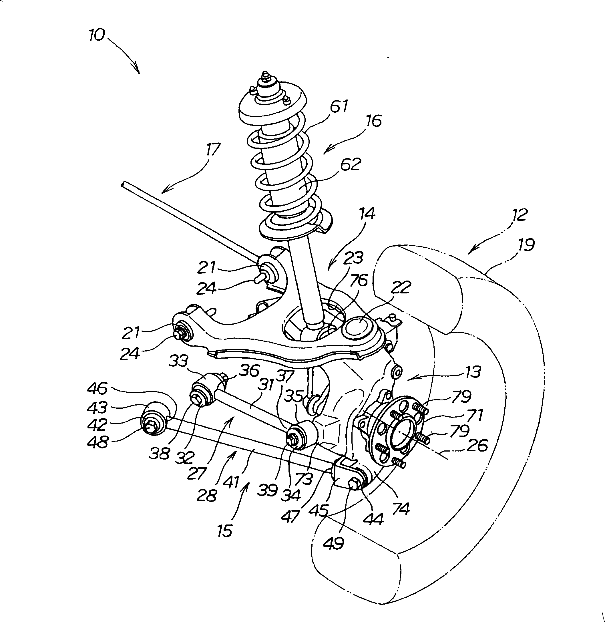
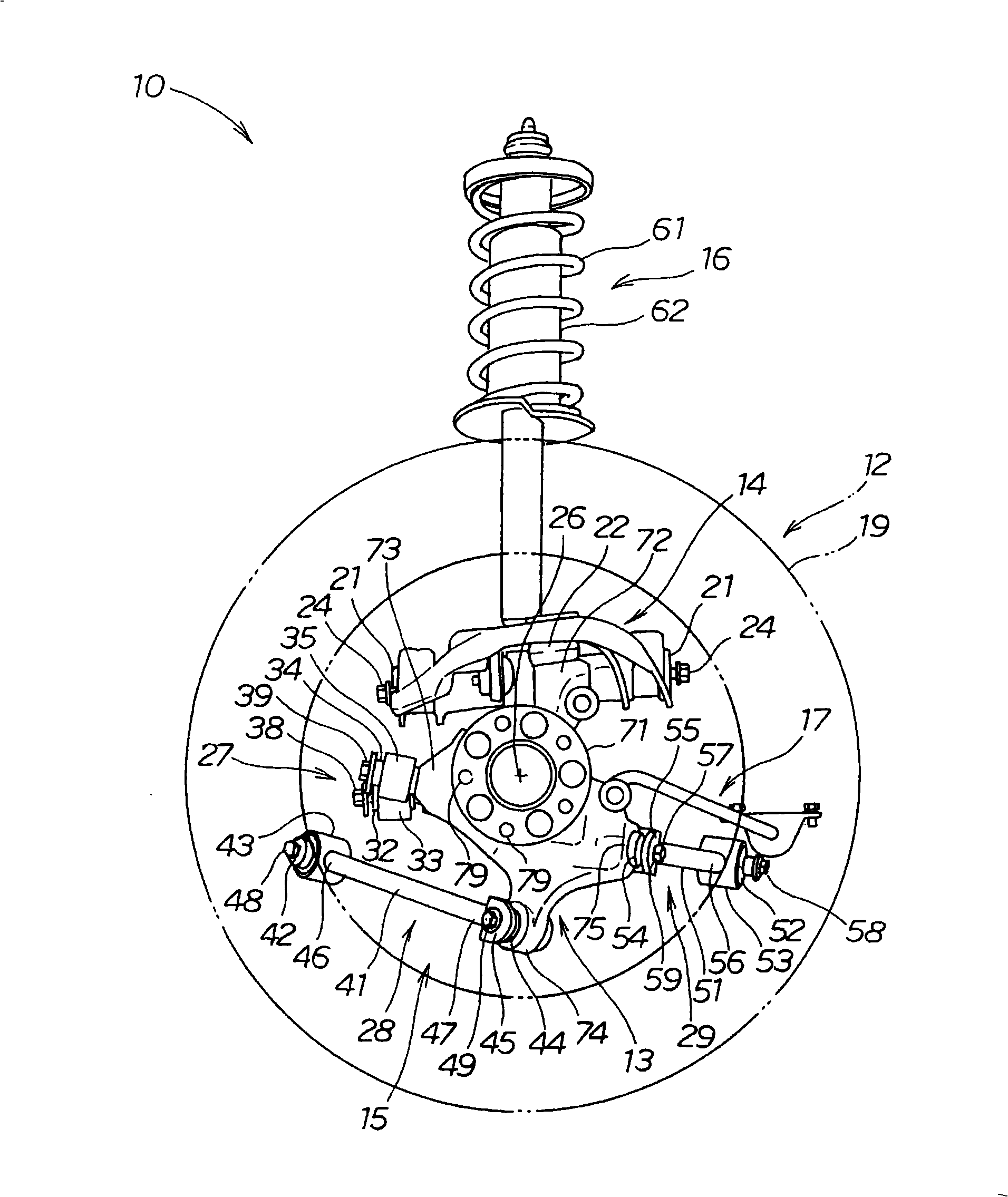
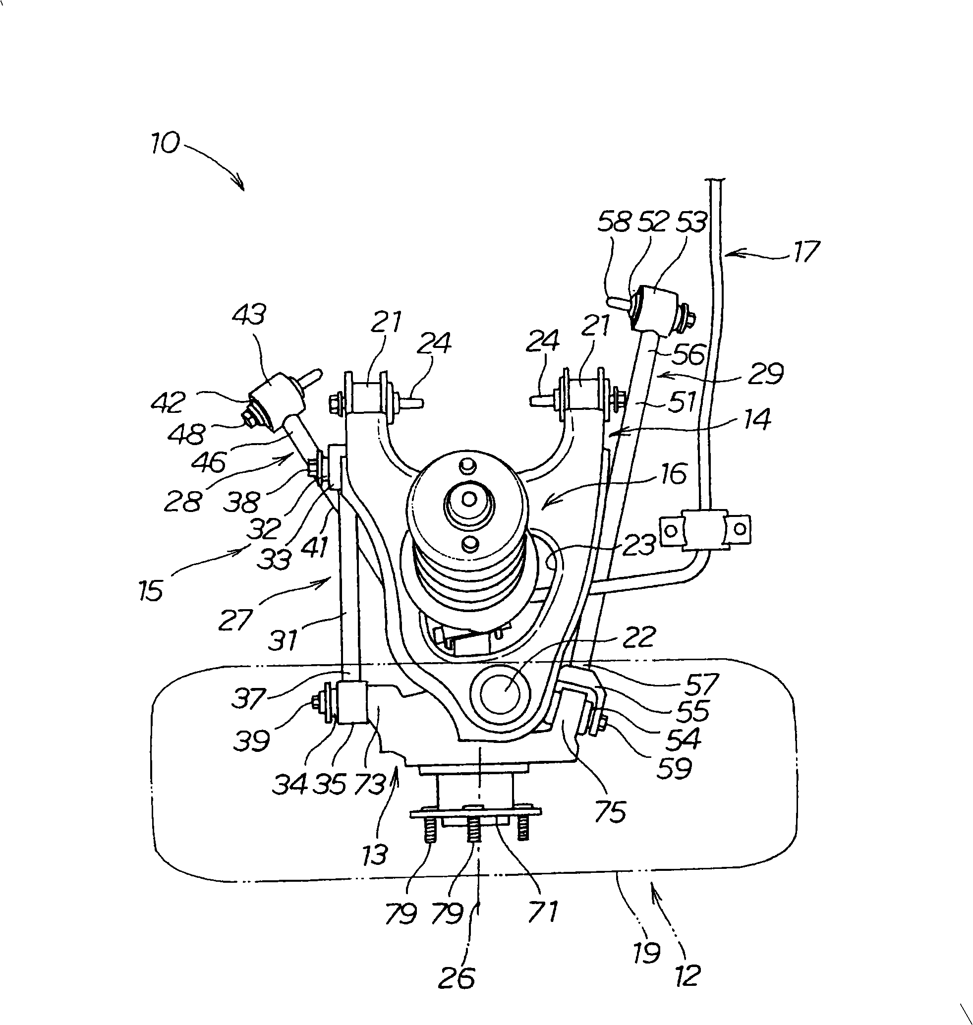
[0043] figure 1 is a perspective view of the vehicle suspension device of the present invention, figure 2 yes figure 1 A side view of the suspension device for the vehicle shown, image 3 yes figure 1 A top view of the vehicle suspension shown, Figure 4 yes figure 1 Rear view of the suspension for the vehicle shown.

[0044] Such as Figure 1 ~ Figure 4 As shown, the vehicle suspension device 10 is the rear suspension of the right rear wheel (wheel) 12, and is composed of the following parts: the joint 13 on which the wheel 12 is rotatably mounted; The upper arm 14 on the upper part of 13; the lower arm group 15 extending from the side of the vehicle body to the outside of the width of the vehicle body and supporting the lower part of the joint 13; the buffer that overlaps the ...


PUM


Abstract

A vehicle suspension apparatus 10 includes a plurality of arms 14, 27 to 29 respectively extending from the side of a vehicle body, and a knuckle 13 swingably supported on the leading ends of these arms 14, 27 to 29 for swingably mounting a wheel 12 thereon. The arm 27 includes a straight arm portion 31, a first rubber bush 32 provided on one end of the arm portion 31 and a second rubber bush 34 provided on the other end of the arm portion 31. And, the center lines C1 and C2 of the first and second rubber bushes 32 and 34, when they are viewed from the axial direction of the arm portion 31, are set to have a predetermined angle of inclination between them.

Description

technical field [0001] The present invention relates to a suspension device for a vehicle that eases an input from a road surface by moving a vehicle up and down and ensures stability (stability) of the vehicle. Background technique [0002] As suspension devices for vehicles, suspension devices such as a double wishbone type and a multi-link type are known. [0003] Such a suspension device for a vehicle is generally adopted by changing the design of the suspension according to the application. [0004] As such a suspension device for a vehicle, a multi-link type suspension device supporting a rear wheel is known (for example, refer to Patent Document 1). [0005] Patent Document 1: Japanese Patent Laid-Open No. 2005-225382 (p. 15, figure 2 ) [0006] based on Figure 7 An outline of the technology of Patent Document 1 will be described. [0007] Figure 7 It is a figure explaining the basic structure of the conventional vehicle suspension device. [0008] The vehicl...

Claims


Application Information

Patent Timeline
Patent Type & Authority Applications(China)
IPC IPC(8): B60G3/18
CPCB60G2204/129B60G2200/18B60G2200/184B60G2206/10B60G3/20B60G2206/124B60G2204/41B60G2204/148B60G2204/143B60G2200/446B60G2202/135B60G2206/017B60G2202/312B60G2206/50
Inventor 平井秀树
Owner HONDA MOTOR CO LTD
Learn More