Transmission type sluice turning apparatus

A transmission type, power device technology, applied in water conservancy engineering, marine engineering, coastline protection, etc., can solve the problems of local loss of water flow, difficult production, huge opening and closing devices, etc., to avoid supporting structures and lifting devices, installation and maintenance. Simple and easy, reduce the effect of civil structure

Inactive Publication Date: 2009-01-28
黄国宏
View PDF0 Cites 2 Cited by
  • Summary
  • Abstract
  • Description
  • Claims
  • Application Information

AI Technical Summary

Problems solved by technology

The shortcomings of the above gate devices are: the butterfly valve composed of a cylindrical shell, a disc-shaped valve leaf and a valve leaf shaft that passes through the valve leaf and passes through the cylindrical shell and is connected to the operating mechanism. When the valve composed of shell, door leaf, door leaf groove and operating mechanism is used in a flow channel with a large flow area, the shell, valve leaf or door leaf is difficult to cast and turn.
Moreover, the door leaf groove will cause a large local loss to the water flow
The plane gate installed in the gate slot cannot be removed when freezing or foreign matter jams in the gate slot, making it impossible to open and close, and requires a huge opening and closing device
The curved gate supported by the supporting hinge has a huge structure, is difficult to manufacture, and requires high installation requirements.
The siphon chamber structure works by the siphon principle, although the water breaks off quickly and there is no leakage, but because of its huge structure, it takes a long time to pump out the air in the siphon chamber, so it is difficult to implement in a large flow channel
The automatic overturning gate supported by the hinge and automatically opened and closed by the water pressure difference not only has poor working reliability, but also the pier on which the hinge is installed seriously affects the flow capacity of the water flow, so it is not widely used

Method used


Image

  • Transmission type sluice turning apparatus
  • Transmission type sluice turning apparatus
  • Transmission type sluice turning apparatus

Examples


Embodiment Construction

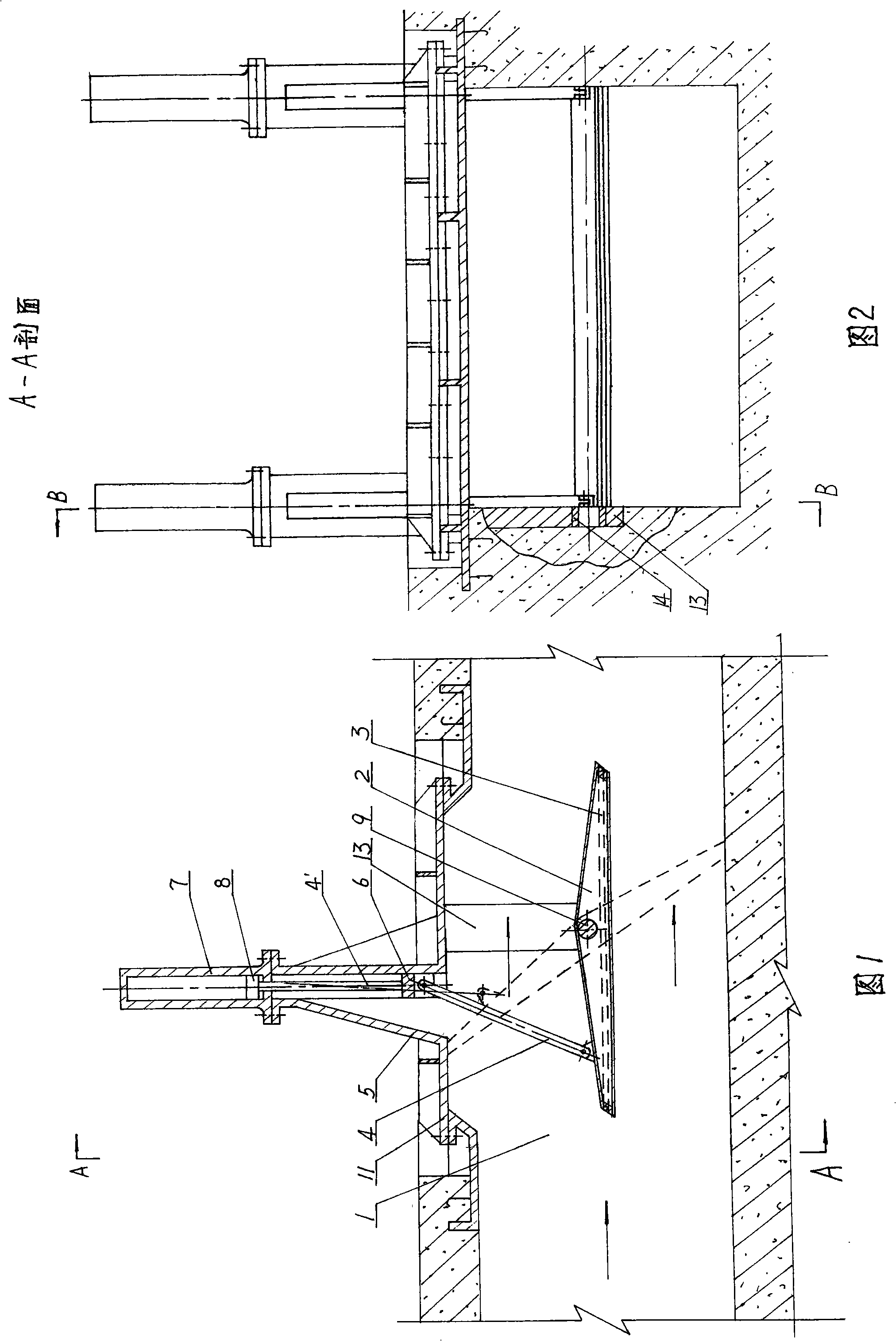
[0027] 1 and 2 show a first embodiment of the invention. This embodiment describes in detail the structure of a transmission-type reversing gate device installed in a giant pressurized flow channel.

[0028] As shown in Fig. 1 and Fig. 2: a top cover 11 that can be placed in a rectangular gate 2 is provided on the top of the rectangular pressure flow channel 1, and rectangular grooves corresponding to each other are respectively provided on both sides of the flow channel 1. Both ends of the gate shaft 9 of the rectangular gate 2 are respectively fitted with a bushing 14 and a pressure block 13 whose shape matches the rectangular groove. When the gate 2 is hoisted into the flow channel 1, the pressing blocks 13 at both ends of the gate shaft 9 are respectively placed in the grooves on both sides of the flow channel 1, and the top cover 11 is installed. Air shroud seals 3 are installed around the perimeter of the rectangular gate 2 . Both sides of the front end of the rectangu...


PUM


Abstract

The invention discloses a drive-typed turning strobe device which relates to a strobe device that quickly and fully blocks water current in a flow channel or adjusts the excess flow rate. The device is composed of a rotatable strobe which is installed in the flow channel, a transmission component arranged at one end of the strobe and a power plant thereof, or a power plant arranged at one of the strobe and a transmission component thereof. The device not only has simple and reasonable structure as well as safe and reliable working performance, but also convenient and simple production, installation and maintenance. Furthermore, the device can also adapt to various large excess flow channels.

Description

Technical field [0001] The invention relates to a transmission-type reversing gate device for quickly and completely cutting off water flow or regulating its overflow flow in a flow channel. Background technique [0002] At present, the devices used to block or adjust the flow in the pressurized flow path (that is, the closed flow path) mainly include butterfly valves, valves, etc.; in the non-pressure flow path (that is, the open flow path) The devices used to cut off or adjust the flow passage mainly include plane gates, arc gates and siphon chambers. And there is also an overturning gate that automatically opens and closes around the support hinge. The shortcomings of the above gate devices are: the butterfly valve composed of a cylindrical shell, a disc-shaped valve leaf and a valve leaf shaft that passes through the valve leaf and passes through the cylindrical shell and is connected to the operating mechanism. When the valve composed of shell, door leaf, door leaf gr...

Claims


Application Information

Patent Timeline
Patent Type & Authority Applications(China)
IPC IPC(8): E02B7/40E02B7/46
Inventor 黄国宏
Owner 黄国宏
Why Eureka
Try Eureka