Scroll type booster

一种增压装置、涡轮式的技术,应用在用于弹性流体的泵送装置的部件、旋转活塞式泵、液体变容式机械等方向,能够解决使用大型电磁铁、未必现实、涡轮式压缩机构造复杂等问题,达到抑制不稳定情况、顺畅防自转、旋转动作稳定的效果

Inactive Publication Date: 2009-01-28
HITACHI LTD
View PDF2 Cites 9 Cited by
  • Summary
  • Abstract
  • Description
  • Claims
  • Application Information

AI Technical Summary

Problems solved by technology

However, in this case, it is inevitable to use a large and expensive electromagnet, which may not be realistic from the viewpoint of cost and effect.
[0013] Moreover, in such a case, since the electric wiring for supplying power to the electromagnet must be installed, for example, inserted into the fixed turbine side, the structure of the turbo compressor becomes complicated, and it is difficult to achieve small size and weight reduction. The problem

Method used


Image

  • Scroll type booster
  • Scroll type booster
  • Scroll type booster

Examples


Embodiment Construction

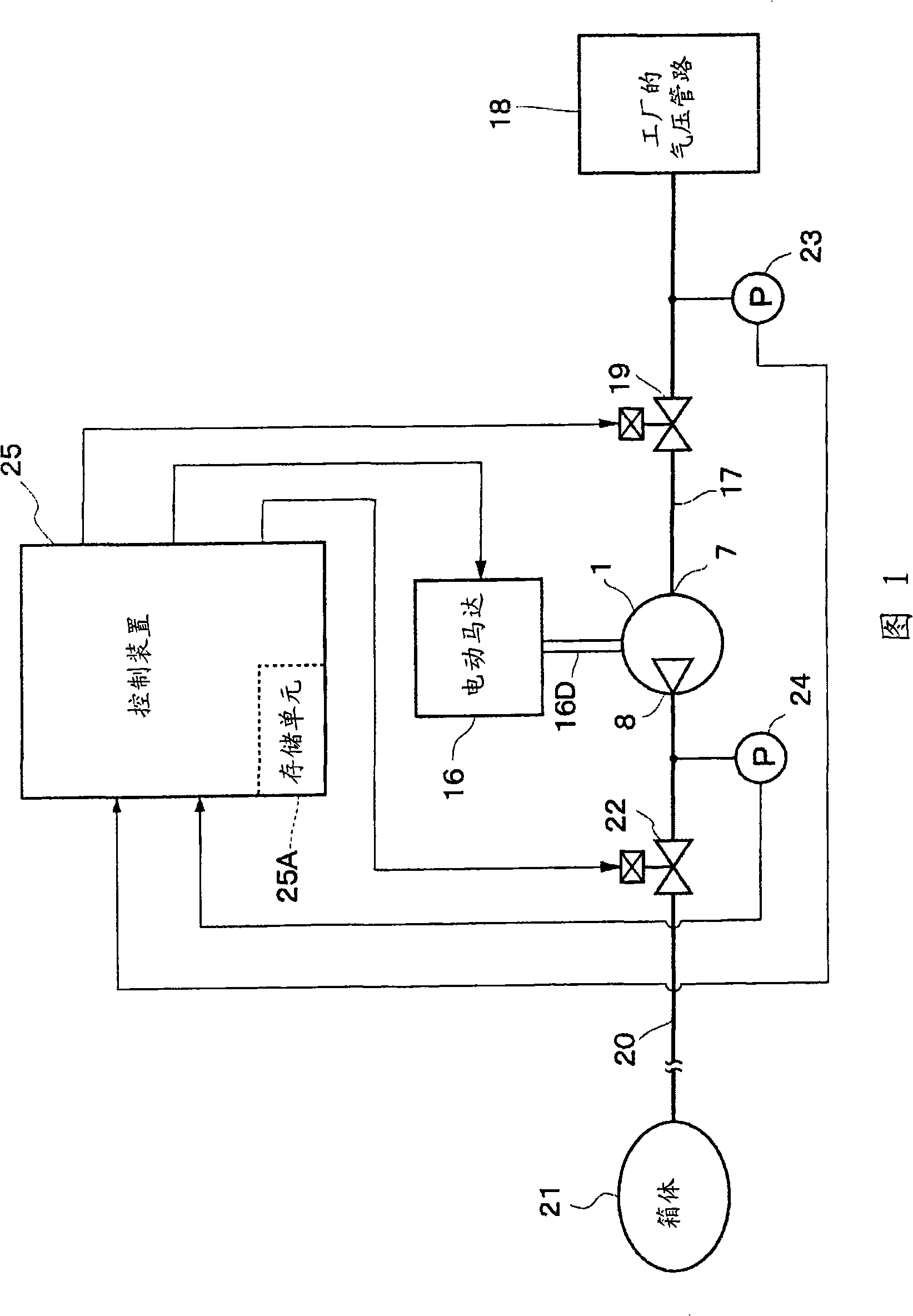
[0051] Hereinafter, the turbocharger according to the embodiment of the present invention will be described in detail with reference to the accompanying drawings as an example when it is used as a supercharger (booster) in a pneumatic pipeline of a factory.

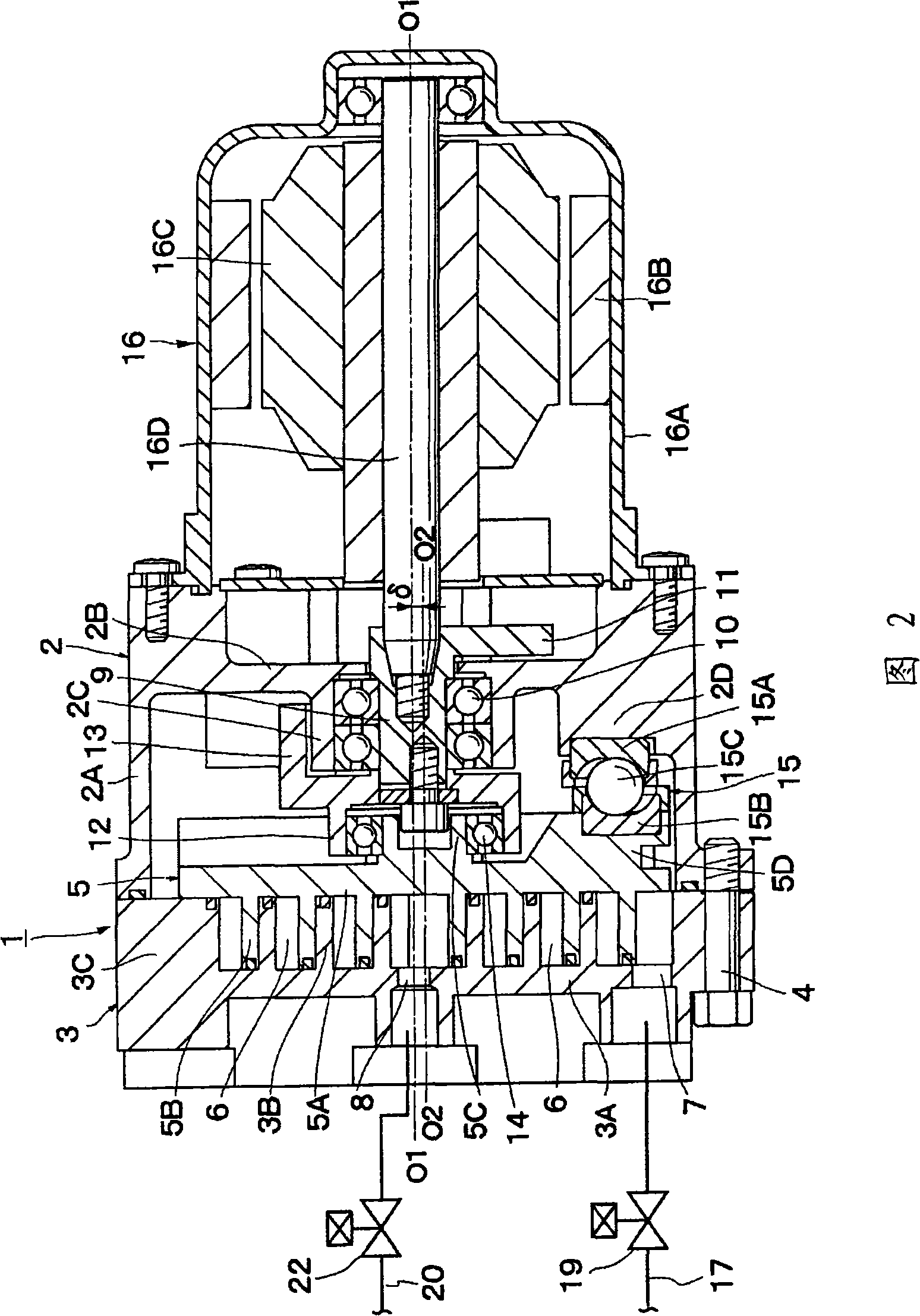
[0052] Here, Figure 1 to image 3 The first embodiment of the present invention is shown. In the figure, 1 is a turbo type compressor main body (hereinafter referred to as compressor main body) constituting a turbo type compression mechanism, and 2 is a cover constituting an outer casing of the compressor main body 1. As shown in FIG. 2 , the cover body 2 is Formed as a bottomed cylindrical body that opens on one side in the axial direction. Further, on the other side in the axial direction of the cover body 2, an electric motor 16 having a drive shaft 16D described later is detachably attached on the axis line O1-O1.

[0053] At this time, the cover body 2 is generally formed to have: a cylindrical portion 2A opened on ...


PUM


Abstract

A scroll type booster ensures a noiseless structure by reducing operation sound using a scroll type compressor as a booster and an easy start-up operation. An electromagnetic valve at an intake side is provided between an intake port of a compressor body and a pneumatic line at an intermediate position of an intake pipe. The electromagnetic valve is opened / closed by the control unit. When the valve is opened, a communication of the intake port of the compressor body and the pneumatic line is allowed. When the valve is closed, the communication between the intake port and the pneumatic line is blocked. Under a start-up control of the compressor body, the electromagnetic valve at the intake side is opened to communicate the pneumatic line in the plant with the intake port of the compressor body for power supply to an electric motor to drive an orbiting scroll. The rattle of the orbiting scroll by an amount equal to the axial gap (play) is suppressed before starting a compression operation.

Description

technical field [0001] The present invention relates to a turbocharger suitable for use as a supercharger, which is installed in connection with, for example, an air pressure line in a factory and boosts the pressure of a fluid such as air as needed. Background technique [0002] Generally, in a factory where a plurality of pneumatic equipment is installed, pneumatic piping (piping) is used to connect each pneumatic equipment, and the compressed air discharged from an air compressor used as a pressurized air source is sent to each pneumatic equipment through the pneumatic piping. The structure of the machine supply. Also, there is known a structure in which the air pressure in the pipeline is doubled by using, for example, a reciprocating compressor called a booster compressor on the downstream side of such a pneumatic pipeline (for example, refer to Patent Document 1). . [0003] Patent Document 1: Japanese Patent Laid-Open No. 2007-51614 [0004] However, this type of r...

Claims


Application Information

Patent Timeline
Patent Type & Authority Applications(China)
IPC IPC(8): F04C18/02F04C28/24F04C29/12F04C29/00F15B3/00
CPCF04C28/06F04B49/022F04C2/025F04B49/03F04C18/0215
Inventor 岩野公宣驹井裕二坂本晋水越绫
Owner HITACHI LTD
Why Eureka
Try Eureka