
Device for measuring the tension in a metallic strip

A metal belt and tension technology, which is applied in the field of devices with tension, can solve the problems of interfering with the measuring device and the inability of the table to obtain strength, and achieve the effect of high resistance to bending force

Inactive Publication Date: 2011-03-09
SMS DEMAG AG
View PDF1 Cites 0 Cited by
  • Summary
  • Abstract
  • Description
  • Claims
  • Application Information

AI Technical Summary

Problems solved by technology

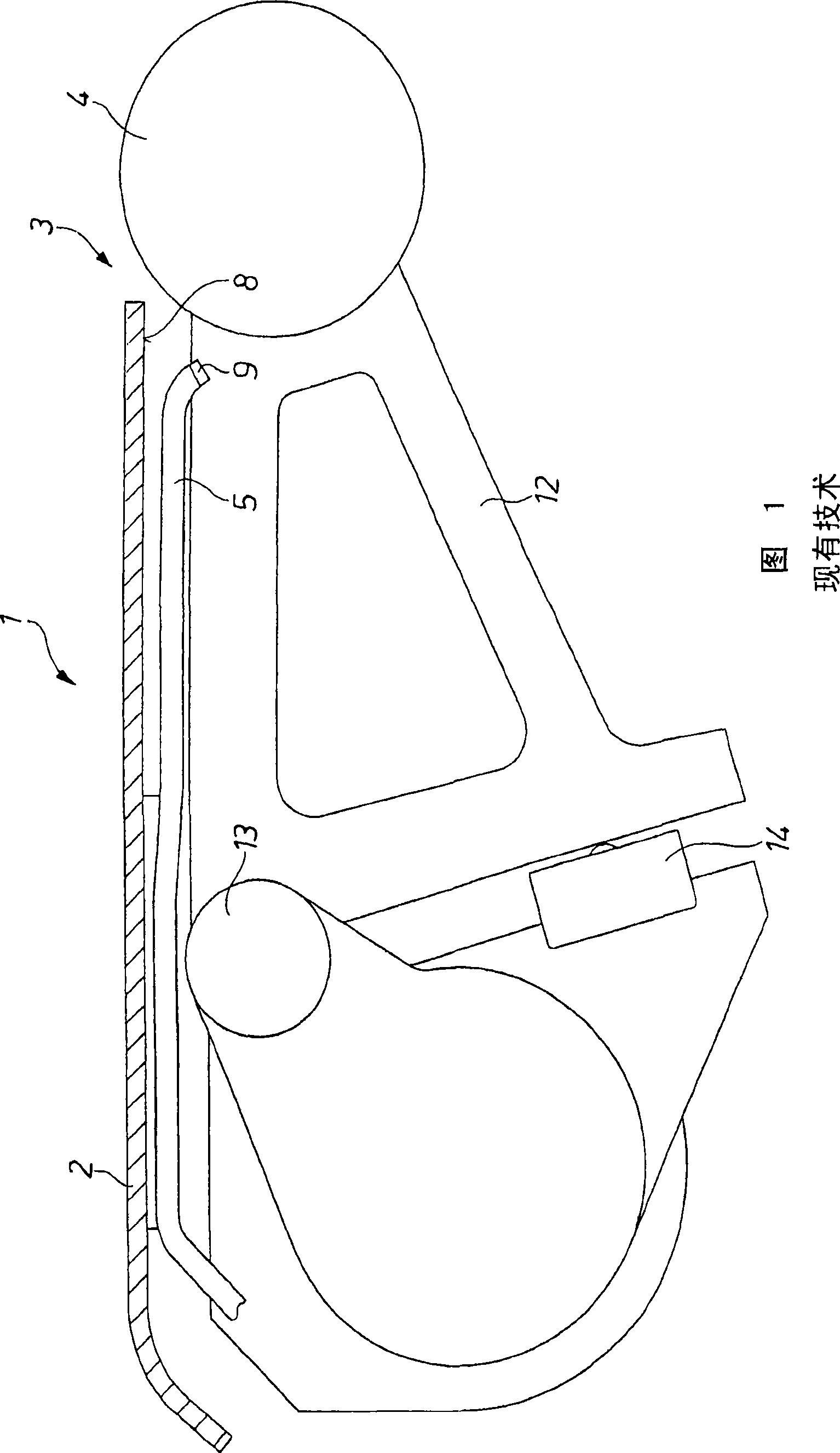
As a result, the table does not acquire sufficient strength and may bend due to mechanical or thermodynamic loading to such an extent that the function of the measuring device arranged below the table for determining the deflection of the measuring rollers is disturbed.

Method used


Image

  • Device for measuring the tension in a metallic strip
  • Device for measuring the tension in a metallic strip
  • Device for measuring the tension in a metallic strip

Examples


Embodiment Construction

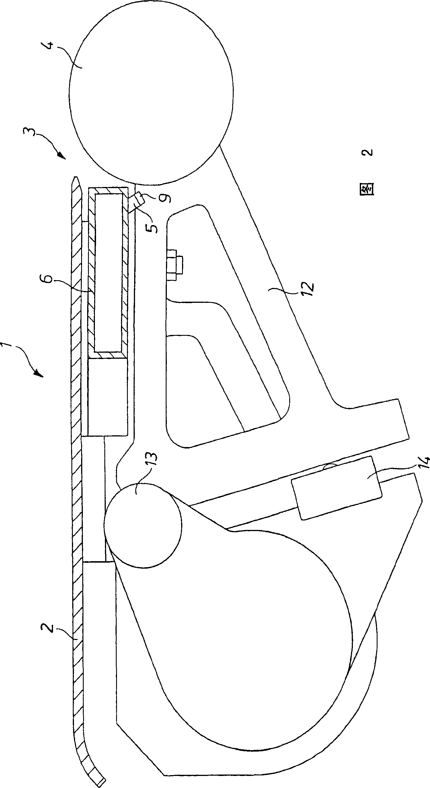
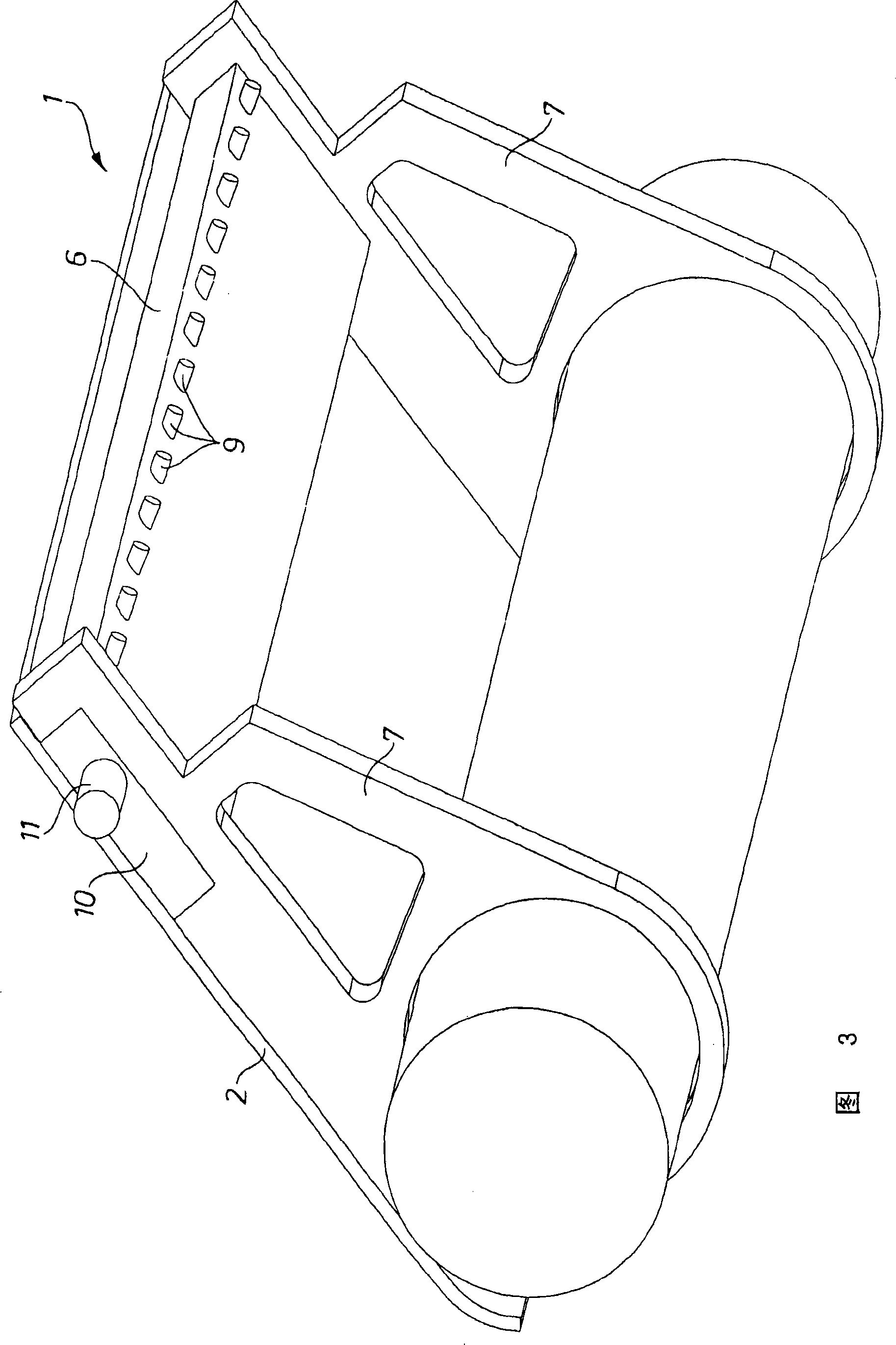
[0020] A device 1 for measuring the strip tension of a steel strip can be seen in the drawings, the steel strip itself not being shown. In its conveying direction, the steel strip passes over a table 2 which forms a flat surface against which the steel strip rests. Measuring elements in the form of measuring rollers 4 are arranged on the front edge 3 of the table. The measuring rollers are each arranged at the end of a support arm 12 , wherein the support arm 12 is mounted in a bearing carrier 13 . One end of the support arm 12 presses against the measuring box 14, so that it can be determined how far the measuring roller 4 is pressed down due to the tension in the steel strip. This provides the possibility to measure the web tension via the measuring elements 4 , 12 , 14 .

[0021] Since the passing steel strip is hot, the measuring roller 4 must be cooled sufficiently for this purpose. For this purpose, a cooling element 5 is provided which extends from a cooling water su...


PUM


Abstract

The invention relates to a device (1) for measuring the tension in a metallic strip, in particular in a steel strip, which has a planar, sheet-like table (2), over which the metallic strip can run and at the one end (3) of which a multiplicity of measuring elements (4) suitable for measuring the tension of the strip are arranged, wherein cooling elements (5) are provided, arranged under the table(2), and allow cooling liquid, in particular water, to be directed into the region of the measuring element (4). To provide a simple means for preventing the table from bending, it is provided according to the invention that the cooling elements (5) have a box-shaped cooling liquid tank (6), which is arranged on both sides of the metallic strip on at least one support element, wherein the table (2) rests indirectly or directly with its underside on the box-shaped cooling liquid tank (6).

Description

technical field [0001] The invention relates to a device for measuring strip tension in metal strips, especially steel strips, which has a flat, planar table through which the metal strip can run, and at one end of which there is a A plurality of measuring cells suitable for measuring the tension of the strip, in which a cooling element is arranged, is arranged below the table and by means of which cooling fluid, in particular water, can be introduced into the region of the measuring cells. Background technique [0002] Devices of this type are known in order to be able to perform measurements on rolled steel strips in the flat state, in particular under tension. Measuring rollers are usually used here as measuring elements, which press against the underside of the strip passing through the table in the conveying direction. The strip tension can be inferred based on the measured deflection of the measuring roll in the direction of the surface normal of the steel strip. [...

Claims


Application Information

Patent Timeline
IPC IPC(8): B21B38/06G01L5/04G01B5/28
Inventor M・基平M・图施霍夫M・埃本贝克H・尼休斯
Owner SMS DEMAG AG
Learn More