
Rack lamp, panel type lamp stamping machine and stamping technique thereof

A technology of stamping processing and lamps, which is applied in the field of metal stamping processing, can solve the problems of low adaptability and flexibility, high total cost, and poor quality controllability, so as to increase flexibility and adaptability, improve stamping processing efficiency, The effect of simple equipment manufacturing and maintenance

Inactive Publication Date: 2009-02-04
惠州雷士光电科技有限公司
View PDF0 Cites 22 Cited by
  • Summary
  • Abstract
  • Description
  • Claims
  • Application Information

AI Technical Summary

Problems solved by technology

[0003] In the current industry, the production of the above two processing methods is low in efficiency, relatively poor in quality controllability, insufficient material utilization rate, difficult to transfer semi-finished products, complicated management of finished products, and waste of a lot of manpower and material resources.
Taking bracket lamps as an example, the specific stamping processing steps are as follows: the first method has low technical content of molds, complicated processes, a large number of all molds, a large investment in equipment and personnel, high total cost, unstable product quality, and relatively high production efficiency. Low
The mold manufacturing and maintenance of the second method are difficult, the adaptability and flexibility are not high, especially the production efficiency is low and the process is complicated
This production process shows that 22 people are required to complete 11 processes under traditional single-flush production

Method used


Image

  • Rack lamp, panel type lamp stamping machine and stamping technique thereof
  • Rack lamp, panel type lamp stamping machine and stamping technique thereof

Examples


Embodiment Construction

[0028] In order to facilitate the understanding of those skilled in the art, the structural principle of the present invention will be further described in detail below in conjunction with specific embodiments and accompanying drawings:

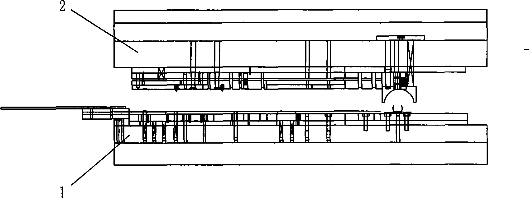
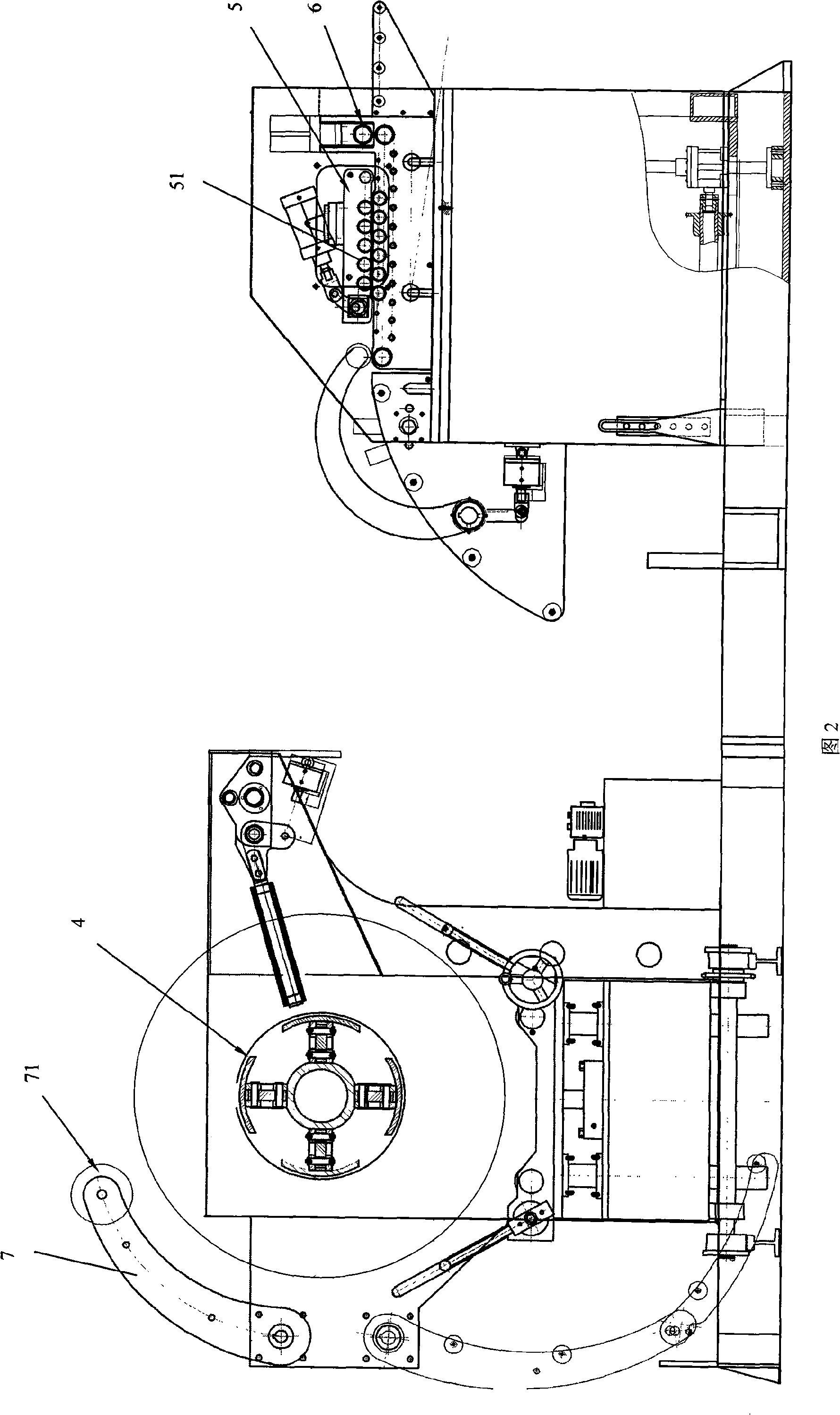
[0029] as attached figure 1 As shown in ~2, the machine tool disclosed in this embodiment is mainly used for stamping bracket lamps and lamp panel lamps. The machine tool includes a feeding servo mechanism for automatically supplying ingredients and a stamping die 3 for stamping blanks.

[0030] The feeding servo mechanism includes a material rack 4 for fixing the coil material, and a straightening table 5 for correcting and leveling the blank is arranged between the material rack 4 and the stamping die 3, and a feeder for pulling the blank into the stamping die 3 is arranged behind the straightening table 5 scroll wheel6. The material rack 4 is also provided with a pressing arm 7, and the end of the pressing arm is provided with a pressing ...


PUM


Abstract

The invention relates to a bracket lamp and a machine tool for processing and punching lamp panel and lamp and a punching processing technology thereof. The machine tool comprises a lower die bed and an upper die bed for installing a punching die. Dies are installed at the inner sides of the lower die bed and the upper die bed. The lower die bed and the upper die bed are installed on a driving mechanism. The lower die bed and the upper die bed are all an integral structure. The dies comprise a blank lance, a reinforcing rib striking die, a blanking guide die, a downwards baling die, a convex hull sizing die, a punched hole, the reinforcing rib striking die, a punching die, a Z-shaped bending die and a bending and molding and a cutting die which are arranged orderly, and each die is arranged transversely. The punching processing technology has the following steps: a) collecting material, b) feeding the material and c) punching transversely and continuously. The equipment is simple for manufacturing and maintaining, improves the flexibility and adaptability of the die structure and has high production efficiency and comparatively stable quality; in the practical production, the existing proposal can only produce 2 to 12 lamps per minute, while the machine tool can produce 48 lamps per minute, so the efficiency is increased by more than 2 times, and the processing cost is reduced by more than 2 times.

Description

technical field [0001] The invention relates to the field of metal stamping processing, in particular to a stamping processing machine tool for bracket lamps and lamp panel lamps and a stamping process for bracket lamps and lamp panel lamps. Background technique [0002] Today's high-precision knowledge technology cooperates with the continuous and rapid development of the industry. For some parts with long workpieces, long working steps or a large number of working steps, the following two processing methods are generally used for stamping processing: the first is to use step-by-step single punching process production, The second is to adopt the general longitudinal continuous mold of the whole module plus the production of the forming mold. [0003] In the current industry, the above two processing methods have low efficiency, relatively poor quality controllability, insufficient material utilization, difficulty in reordering semi-finished products, and complicated managem...

Claims


Application Information

Patent Timeline
IPC IPC(8): B21D35/00B21D43/08B21D37/10
Inventor 吴长江张洪飞
Owner 惠州雷士光电科技有限公司
Learn More