Inspection device, inspection method, inspection system and method of manufacturing color filter

A technology of inspection device and color filter, applied in the direction of measurement device, identification device, optical device, etc., can solve the problems of unsuitable for streak inspection, unsuitable, unsuitable for streak detection, etc.

Inactive Publication Date: 2009-02-04
SHARP KK
View PDF3 Cites 13 Cited by
  • Summary
  • Abstract
  • Description
  • Claims
  • Application Information

AI Technical Summary

Problems solved by technology

[0020] However, the technique of Patent Document 1 is not suitable for detecting the appearance of streaks at a predetermined specific period because the accumulated data is generated by cutting out a part of the two-dimensional data.
In addition, in Patent Document 1, since one-sided inclination irregularity is not taken into consideration at all, there is a problem that one-sided inclination irregularity (defect in handling of good products) is mistakenly detected as a defect
[0021] In addition, in the technique of Patent Document 2, since the shape of the surface of the object is analyzed using the period position at which the frequency spectrum has a maximum value, it is not suitable for performing evaluation involving a predetermined specific period
In addition, in Patent Document 2, as in the above-mentioned technique of Patent Document 1, one-sided inclination irregularity is not considered at all, so there is a problem of being affected by one-sided inclination irregularity.
[0022] In addition, since the brightness difference between the part where streaks occur and the part where no streaks do not occur is small, it is difficult to detect streaks after binarization
That is, the technique of Patent Document 3 is not suitable for streak inspection
In addition, since the patent document 3 does not consider the one-sided tilt irregularity at all, this method may falsely detect the one-sided tilt irregularity

Method used


Image

  • Inspection device, inspection method, inspection system and method of manufacturing color filter
  • Inspection device, inspection method, inspection system and method of manufacturing color filter
  • Inspection device, inspection method, inspection system and method of manufacturing color filter

Examples


Embodiment approach 1

[0046] [Constitution of inspection system]

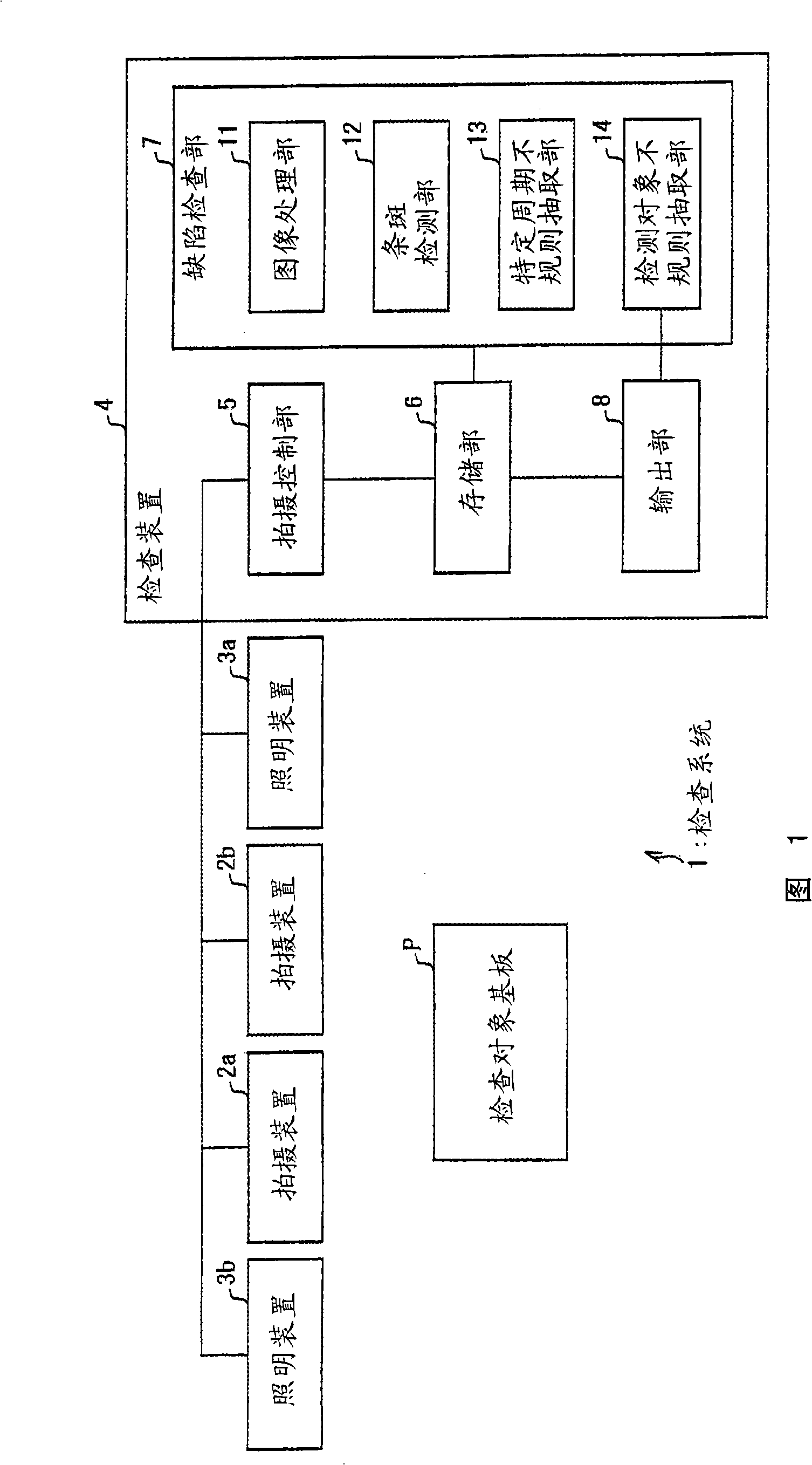
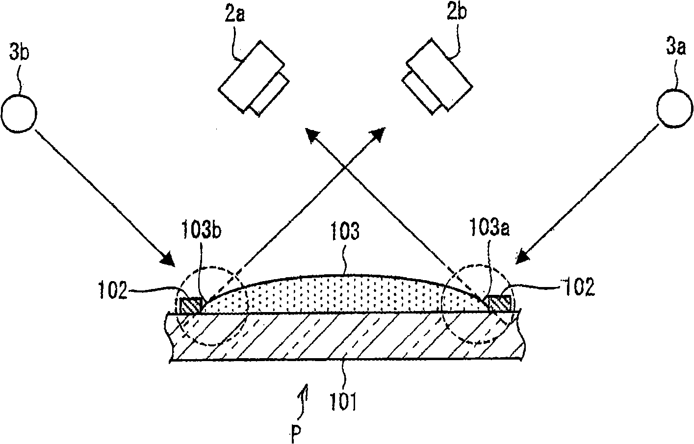
[0047] Next, an embodiment of the present invention will be described with reference to FIGS. 1 to 7 . First, an overview of an inspection system 1 according to the present embodiment will be described with reference to FIG. 1 . FIG. 1 is a block diagram showing an overview of an inspection system 1 . As shown in the figure, the inspection system 1 uses an inspection target substrate P as an inspection object, and includes an imaging device 2 a , an imaging device 2 b , an illumination device 3 a , an illumination device 3 b , and an inspection device 4 .

[0048] Here, it is assumed that the inspection target substrate P constituting the inspection target of the inspection system 1 is a color filter substrate. In the following description, the so-called color filter refers to an optical filter that allows a display device to perform color display by passing light of a specific wavelength. In addition, a color filter is formed by...

Embodiment approach 2

[0103] In the above-mentioned embodiment, an example was shown in which streaks were detected from one image L and one image R, but in this embodiment, the image L and the image R are respectively divided into a plurality of region, and detect instances of streaks in units of segmented regions. By dividing the image L and the image R into a plurality of regions, the detection accuracy of streaky spots can be improved. In addition, the same reference numerals are assigned to the same configurations as those in the above-mentioned embodiment, and description thereof will be omitted.

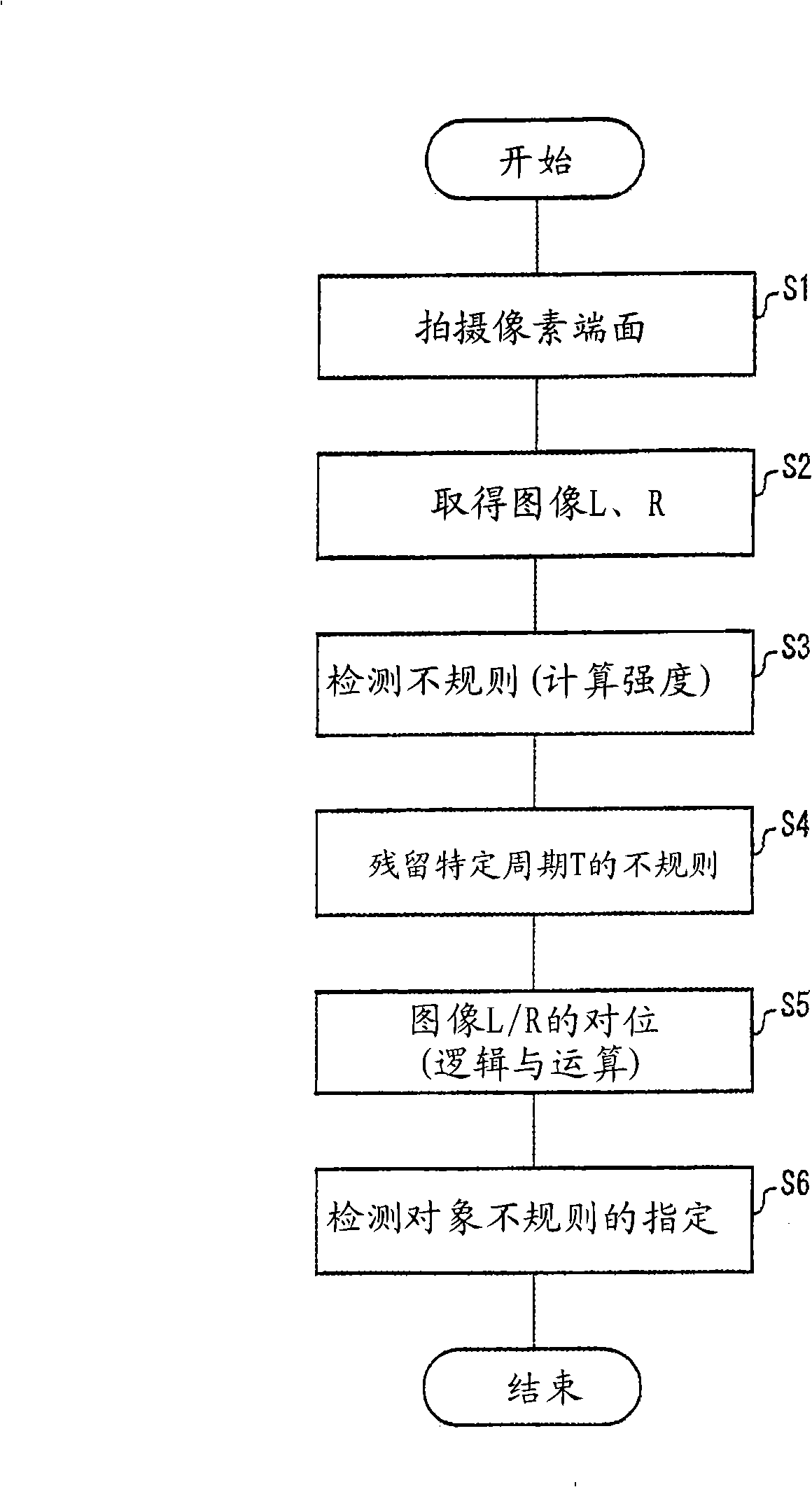
[0104] The inspection system 1 of this embodiment has the same configuration as that of the above-mentioned embodiment except that the inspection device 4 includes a region dividing unit (region dividing means), and the processing flow for detecting streaky spots is also the same as that of the above-mentioned embodiment. image 3 The processing flow shown is the same. Therefore, below, first, th...


PUM


Abstract

The invention relates to an inspection device, an inspection method, an inspection system and a manufacturing method of a color filter. The inspection device of the present invention includes: a linear irregularity detecting section for detecting linear irregularities individually in an image L of dots on a substrate being inspected by projecting light from a first direction and in an image R of the dots by projecting light from a second direction, which differs from the first direction; a specific-cycle irregularity extracting section for extracting linear irregularities detected at predetermined intervals T in the individual mages L and R, the intervals being taken vertical to the linear irregularities on the substrate; and a detection-target-irregularity extracting section for extracting a linear irregularity detected in both the images L and R as a detection-target linear irregularity. The device therefore is capable of detecting only linear irregularities of a specific cycle which are caused by the presence of dots having irregular thickness when compared to a dot with normal thickness.

Description

technical field [0001] The present invention relates to an inspection device and the like for detecting linear irregularities generated in an inspection object at a specific period from an image taken of an undulating end portion of the inspection object having undulations. Background technique [0002] In recent years, the demand for liquid crystal display devices tends to increase while increasing in size. However, in order to further popularize liquid crystal display devices, it is necessary to reduce the cost. In particular, in liquid crystal display devices, there is an increasing demand for cost reduction of color filters (color filters), which have a high proportion of cost. [0003] Recently, a method of forming a color filter based on an inkjet method is attracting attention. In this forming method, a color filter is formed by ejecting R (red), G (green), and B (blue) inks from nozzles of an inkjet head to each pixel. The inkjet method is characterized by a small...

Claims


Application Information

Patent Timeline
Patent Type & Authority Applications(China)
IPC IPC(8): G01N21/956G01B11/00G01B11/24G01M11/00G01N21/88G02B5/20G02F1/13G02F1/1335G09F9/00
CPCG01N2021/8887G01N21/8851G02B5/223G01N2021/9511G01B11/245G01N2021/9513G01N21/95
Inventor 井殿多闻
Owner SHARP KK
Why Eureka
Try Eureka