Determining method for sound field rebuilding plane in acoustics video camera system

A sound field reconstruction and camera technology, applied in radio wave measurement systems, positioning, measuring devices, etc., can solve problems such as the limitation of dynamic sound source and sound source positioning accuracy

Inactive Publication Date: 2009-02-04
TSINGHUA UNIV
View PDF0 Cites 7 Cited by
  • Summary
  • Abstract
  • Description
  • Claims
  • Application Information

AI Technical Summary

Problems solved by technology

The existing acoustic camera system basically uses a fixed sound field reconstruction plane method, which has certain limitations in the positioning of dynamic sound sources and the positioning accuracy of sound sources

Method used


Image

  • Determining method for sound field rebuilding plane in acoustics video camera system
  • Determining method for sound field rebuilding plane in acoustics video camera system
  • Determining method for sound field rebuilding plane in acoustics video camera system

Examples


Embodiment Construction

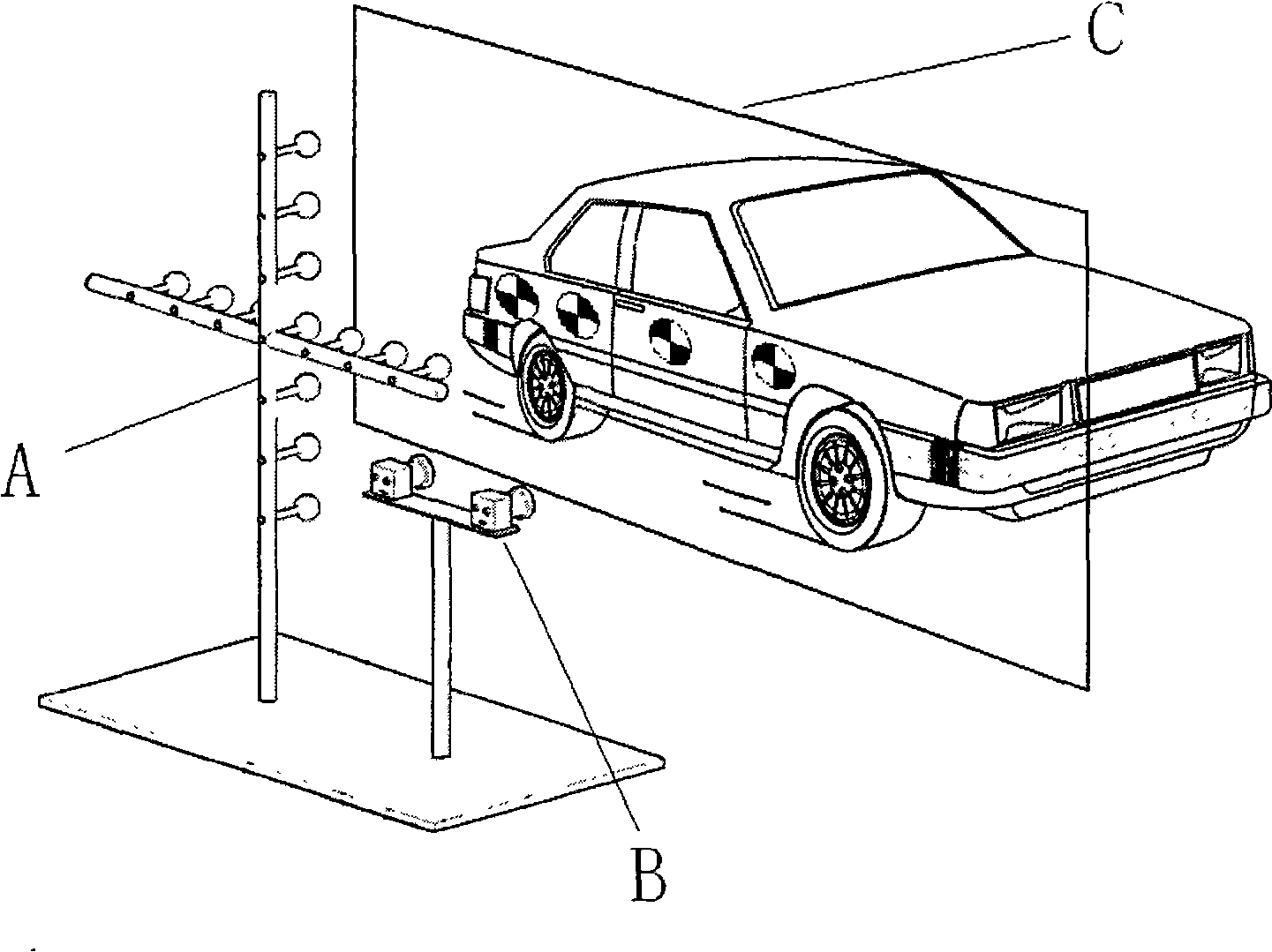
[0033] The method for determining the sound field reconstruction plane in the acoustic camera system proposed by the present invention will be described in detail below with reference to the accompanying drawings. The system that realizes the method of the present invention is as figure 1 Shown:

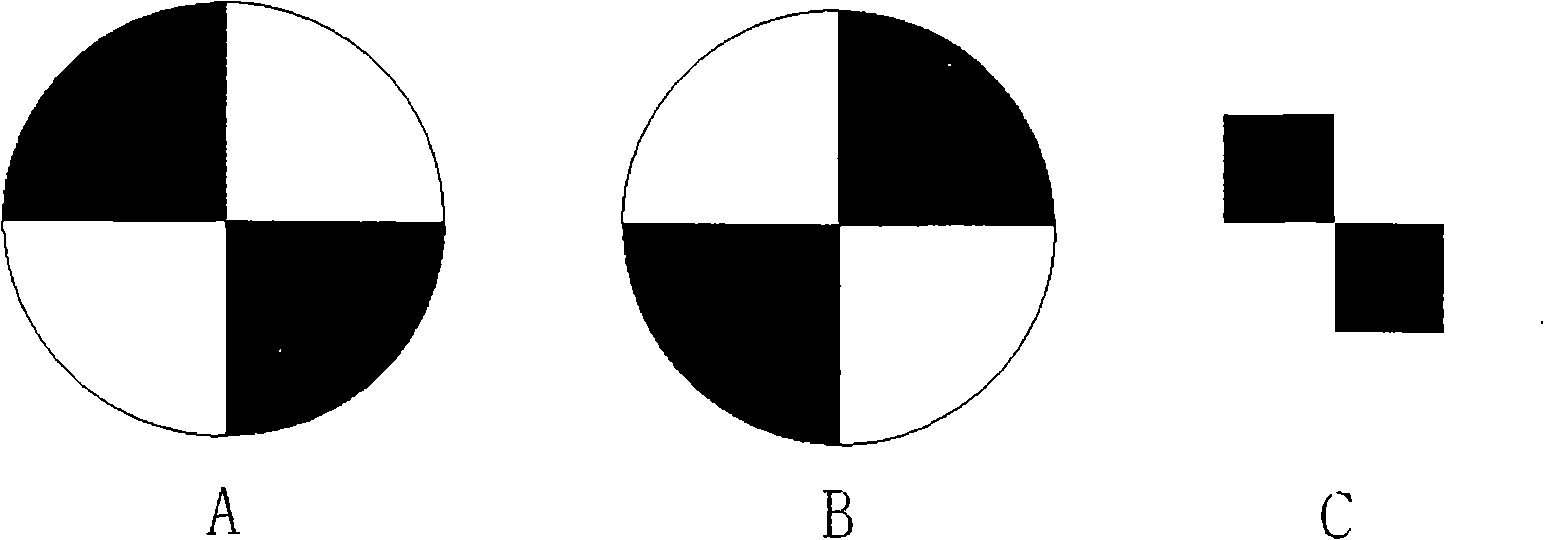
[0034] (1) Paste mark points on the side of the object to be measured, and divide the side of the moving object into two parts, the front and the back. The mark points attached to the front are as follows: figure 2 There are n type 1 mark points shown, and the rear part is attached as figure 2 There are m number of -1 type marker points shown. The marking points are evenly distributed, and the longitudinal spacing is not greater than 20% of the longitudinal size of the object. The selected world coordinate system is a right-handed coordinate system, the positive direction of the x-axis points to the right horizontally, and the positive direction of the y-axis goes vertically upw...


PUM


Abstract

The invention provides an acoustic field reconstruction plane confirming method in an acoustic camera system, belonging to the noise analysis and control technical field. First of all, sign points are pasted on the moving object to be tested; the synchronous images in two cameras in the system go through sign point identification through a template matching method, and the identified result is matched to find the corresponding image-point pairs; the matched image-point pairs are space-oriented through a binocular stereo vision method to obtain the coordinates of the sign points corresponding to the selected coordinate system; then a spatial plane of the sign points is calculated, and the plane serves as the reconstruction plane of the acoustic field. The method provides acoustic field reconstruction plane parameters for the acoustic camera system, and establishes the basis for the integration of the acoustic field images and the video images.

Description

technical field [0001] The invention relates to a method for determining a sound field reconstruction plane in an acoustic camera system, and belongs to the technical field of noise analysis and control. Background technique [0002] The noise of complex moving machinery such as automobiles and trains has a great impact on the environment. Due to the movement, for this type of (multi-sound source) motion noise, it is more difficult to obtain its sound field more accurately, distinguish each sound source, and accurately locate it. The visualization of the sound field can make the positioning and analysis of the noise source more practical, thereby providing a basis for further noise control work, and is of great significance to noise measurement and control work. [0003] In order to improve the efficiency of sound source localization and sound field visualization, and perform sound source analysis more intuitively, in the field of noise analysis in recent years, a method of...

Claims


Application Information

Patent Timeline
Patent Type & Authority Applications(China)
IPC IPC(8): G01S5/00
Inventor 杨殿阁连小珉邵林罗禹贡李兵郑四发李克强王建强
Owner TSINGHUA UNIV
Why Eureka
Try Eureka