Hollow mold for filling cast-in-situ concrete

A technology of hollow carcass and cast-in-place concrete, which is applied to the on-site preparation of building components, formwork/formwork/work frame, building components, etc., which can solve the inconvenience of production, inconvenient assembly line production, and inability to arrange hollow carcass And other issues

Inactive Publication Date: 2009-02-11
湖南邱则有专利战略策划有限公司
View PDF3 Cites 0 Cited by
  • Summary
  • Abstract
  • Description
  • Claims
  • Application Information

AI Technical Summary

Problems solved by technology

But when this kind of hollow carcass is applied to the floor construction, the hollow carcass cannot be accurately arranged in the middle layer of the floor, which affects the construction quality of the floor
For this reason, the patent No. is ZL01215092.4, and the name is "building component" utility model patent. The disclosed building component is a polyhedron, which can be hollow or solid. In order to ensure that this building component is applied to the floor It is arranged in the middle layer of the floor, and the outer wall of the polyhedron is provided with protruding legs, so that when the floor is poured, the legs can ensure that the hollow multi-faceted main cavity is just at the middle layer of the floor. , so as to better solve the above problems, but this kind of building components is inconvenient to make during production, the production efficiency is low, it is not convenient for assembly line production, and the corresponding cost is high

Method used


Image

  • Hollow mold for filling cast-in-situ concrete
  • Hollow mold for filling cast-in-situ concrete
  • Hollow mold for filling cast-in-situ concrete

Examples


Embodiment Construction

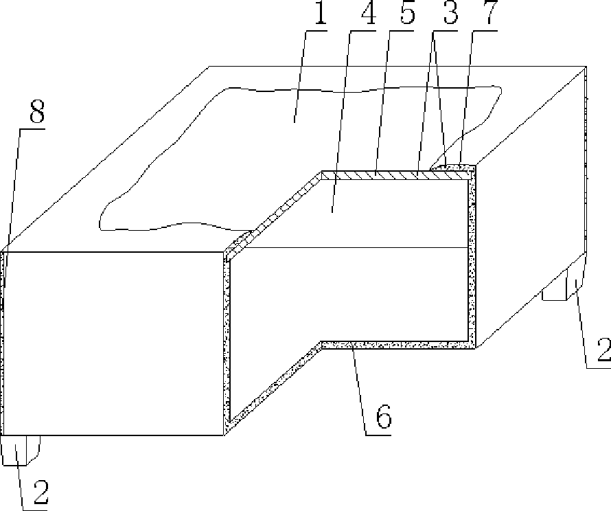
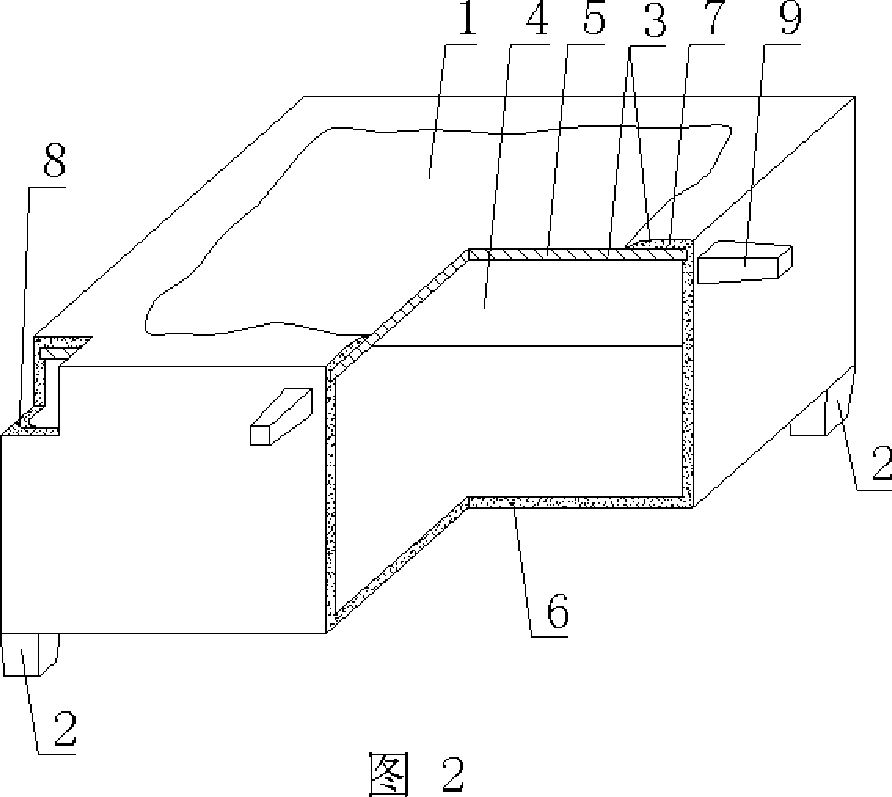
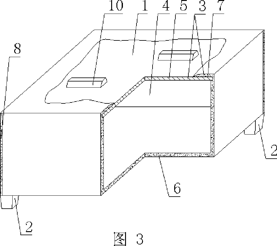
[0061] The present invention will be further described below in conjunction with the accompanying drawings and embodiments.

[0062] As shown in the accompanying drawings, the present invention includes a hollow carcass 1 and a supporting foot 2. The supporting foot 2 is arranged on the outer wall 3 of the hollow carcass 1. The supporting foot 2 is a split foot or a movable foot, and the outer wall 3 is enclosed to form a hollow The hollow carcass 1 of the cavity 4 is characterized in that the hollow carcass 1 is a hexahedron, the hollow carcass 1 is formed by a prefabricated outer wall 5 closing the opening of the basin-shaped embryo body 6, and the prefabricated outer wall 2 is the top outer wall. The outer wall 5 is superimposed with an existing plaster layer 7, and the five-sided embryo body of the basin-shaped embryo body 6 is an integral conjoined embryo body. Within the layer 7 there are reinforcements 12 . In each drawing, 1 is a hollow carcass, 2 is a support foot, 3...


PUM


Abstract

A hollow matrix for cast-in-situ concrete filling comprises a hollow matrix (1) and an arm brace (2), wherein, the arm brace (2) is arranged on outer walls (3) of the hollow matrix (1), the arm brace (2) is a split arm or a movable arm, and the hollow matrix (1) with a cavity (4) is formed by enclosing the outer walls (3). The hollow matrix is characterized in that the hollow matrix (1) is a hexahedron; the hollow matrix (1) is formed by closing an opening of a basin-shaped blank (6) by a prefabricated outer wall (5), a prefabricated outer wall (2) is a top outer wall, the prefabricated outer wall (5) is superposed with an applied-in-situ layer (7), a pentahedral blank of the basin-shaped blank (6) is an integrated connected blank, the blank rims of the pentahedral blank are jointed and cemented, and a joint forms a cementing zone (8), the applied-in-situ layer (7) is internally provided with an reinforcement (12). The hollow matrix is applicable to cast-in-situ reinforced concrete or prestressed reinforced concrete hollow slabs, floors, roofs, walls, foundation slabs and bridges, especially to hollow flat slabs.

Description

[0001] This application is a divisional application of an invention patent application with an application date of September 2, 2004, an application number of 200410155274.4, and a title of "a hollow matrix for filling cast-in-place concrete". (1) Technical field [0002] The invention relates to a hollow matrix for filling cast-in-place concrete. (2) Background technology [0003] At present, the cast-in-place concrete hollow floor is a widely used floor structure. The lightweight permanent tire molds filled in it include various hollow tubes and boxes, and the boxes are hollow or solid. For example, the patent No. ZL99249798.1, which the applicant applied for on November 29, 1999, is a utility model patent named "fiber-reinforced thin-walled member for reinforced concrete filling", which discloses a thin-walled formwork member, including an upper plate, The surrounding side walls, the lower bottom, and the upper plate, the surrounding side walls and the lower bottom form a...

Claims


Application Information

Patent Timeline
IPC IPC(8): E04B5/21E04B5/36E04G11/40E04G15/06
Inventor 邱则有
Owner 湖南邱则有专利战略策划有限公司
Why Eureka
Try Eureka