
Central thread passing pipe twisting machine

A tube stranding machine and wire-type technology, which is applied in the manufacturing of electrical components, circuits, cables/conductors, etc., can solve the problem that the tube stranding machine cannot realize the multi-layer stranding, hard wire or stranded wire stranding. The problem that the wire cannot pass through and the number of twisted cables is not applicable, so as to achieve the effect of small moment of inertia, low equipment failure rate, and reduced equipment energy consumption

Inactive Publication Date: 2009-02-11
FUJIAN NANPING SUN CABLE
View PDF0 Cites 17 Cited by
  • Summary
  • Abstract
  • Description
  • Claims
  • Application Information

AI Technical Summary

Problems solved by technology

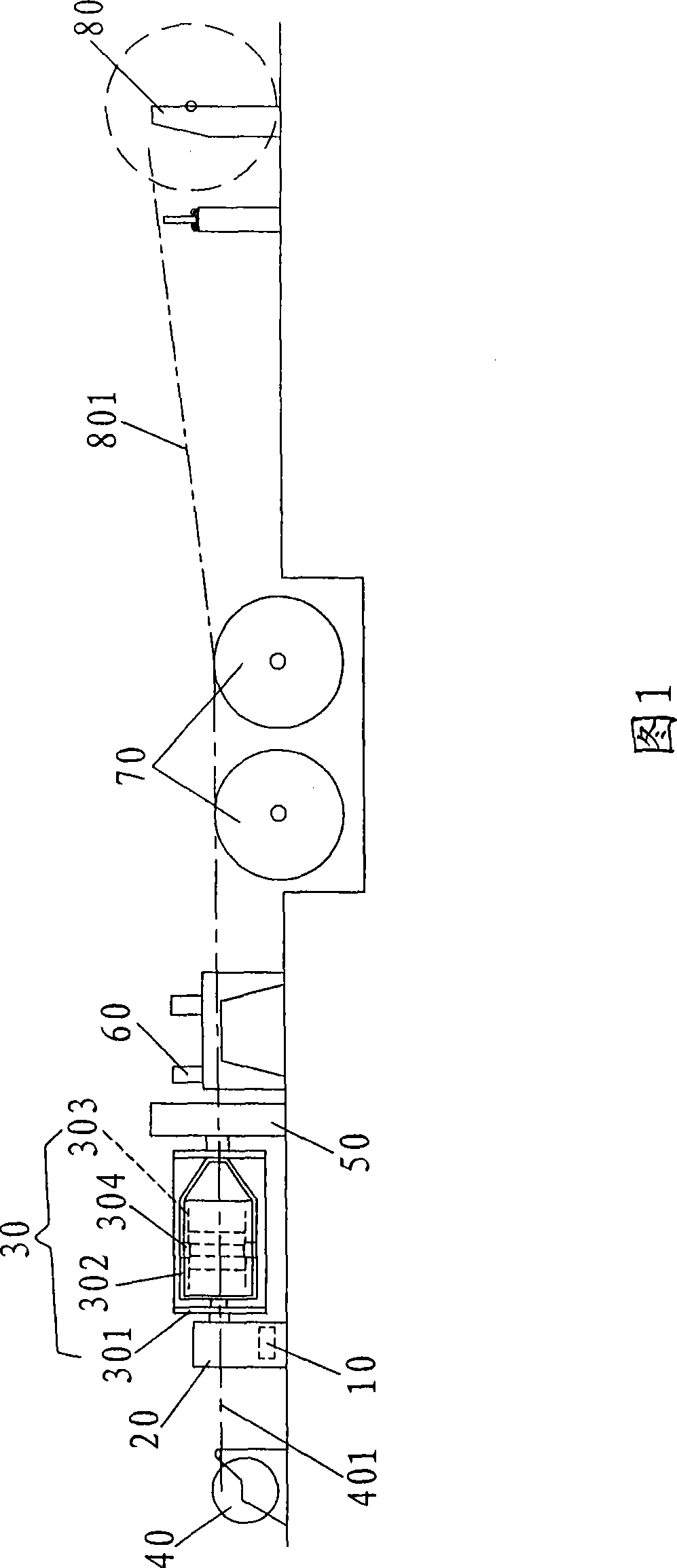
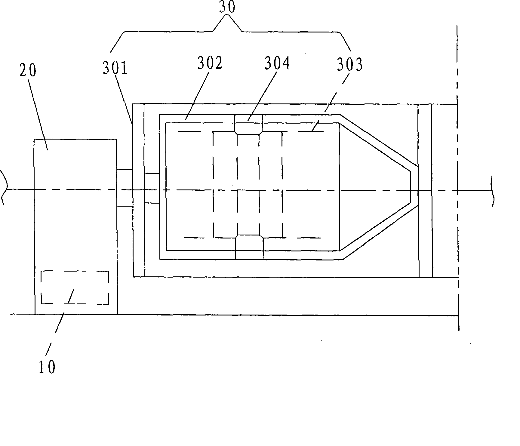
[0003] With regard to the analysis of the traditional pipe stranding machine, it is not difficult to find that although the production efficiency of the traditional pipe stranding machine is very high, the axis of the pay-off reel 302 is 90 to the center line 401 released from the pay-off reel on the central pay-off frame 40 When the center line 401 passes through the twisted body 30, it is blocked by the pay-off reel 302, and the center line cannot be threaded, but can only be threaded through the pipe wall, especially for hard lines or stranded lines, which makes the traditional pipe stranding machine Hard wire or stranded wire stranding and multi-layer stranding cannot be realized, and, limited by the number of coils, only 6 pay-off reels 302 can be installed in the strand 30 (that is, 6 sections of strands, belonging to regular strands), namely Only 7 twisted cables can be produced
Therefore, the traditional tube twisting machine is not suitable for twisting more cables

Method used


Image

  • Central thread passing pipe twisting machine
  • Central thread passing pipe twisting machine
  • Central thread passing pipe twisting machine

Examples


Embodiment Construction

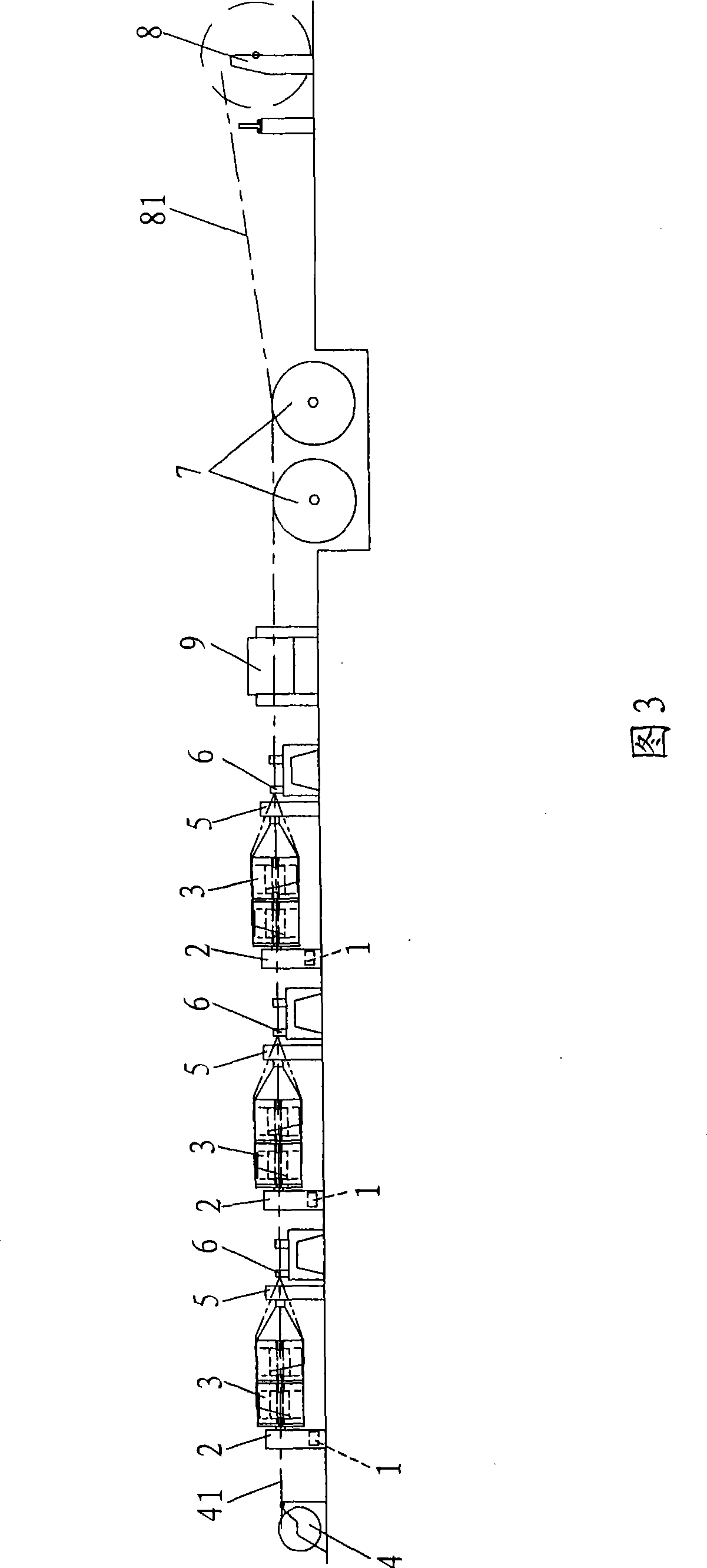
[0050] Referring to Fig. 3, it is a preferred embodiment of the present invention, the central threading type pipe stranding machine mainly includes a motor 1, a gearbox 2, a twisted body 3, a central pay-off frame 4, a wire distribution tray 5, and a wire collection mold 6. Traction machine 7, wire take-up rack 8. The stranded body 3 includes a pipe body 31 and a pay-off reel 33 . The pay-off reel 33 is assembled in the pipe body 31 through the reel clamping device.

[0051] The key of the present invention is as Figure 4 Shown: the axis of the pay-off reel 33 is designed to coincide with the center line 41 (i.e. the center line of the production line) released by the pay-off reel on the center pay-off stand 4, and the corresponding pay-off reel 33 in the twisted body 3 is also equipped with a replacement Guide wheel mechanism 32. In this way, the central hole of the pay-off reel 33 is used for threading when threading, which solves the problem that the traditional tube s...


PUM


Abstract

The invention discloses a central threading type tubular stranding machine, which comprises a motor, a transmission case, a stranding body, a central pay-off stand, a wire separating disk, a wire converging mold, a traction machine, a take-up stand. The stranding body comprises a tubular body and a pay-off disk which is assembled inside the tubular body via a wire coil clamping device, the axial line of the pay-off disk is overlapped with the central line of a production line, a direction changing guide wheel mechanism is also arranged inside the stranding body corresponding to the pay-off disk, the motor is in transmission connection with the tubular body via the transmission case, wires from the pay-off disk change direction via the direction changing guide wheel mechanism, and are converged to the cable converging mold via the cable separating disk and stranded with the central line from the pay-off disk on the central pay-off stand, and the stranded cable product is wound on a winding disk of the take-up stand via the traction machine. The tubular stranding machine is suitable for stranding hard wires or stranded wires and multilayer stranding, especially suitable for stranding compact / non-compact round and fan-shaped wire cores with less than 37 wires, as well as suitable for stranding thin soft wire cores and cabling insulated wires.

Description

technical field [0001] The invention relates to cable core stranding equipment, especially related to the structure of a new type of high-efficiency central threading tube stranding machine, especially suitable for stranding less than 37 tightly compressed and non-compacted circular and fan-shaped cores, and is also suitable for It is suitable for twisting and insulated wires with thin and soft cores. Background technique [0002] Cable core tube stranding machine is a kind of equipment widely used in cable manufacturing and processing. As shown in Figure 1, the traditional pipe stranding machine is mainly composed of a motor 10, a gearbox 20, a twisting body 30, a central pay-off frame 40, a wire distribution plate 50, a wire collection mold 60, a tractor 70, and a wire take-up frame 80 Composition, such as figure 2 As shown, the strand 30 includes a tubular body 301, a cradle 302 and a pay-off reel 303, the pay-off reel 303 is assembled in the tubular body 301 by a reel ...

Claims


Application Information

Patent Timeline
IPC IPC(8): H01B13/02
Inventor 徐建忠庄长兴
Owner FUJIAN NANPING SUN CABLE
Learn More