Earthing mechanism of electronic apparatus

An electronic device and electrical connection technology, applied in the direction of conductive connection, connection, circuit, etc., can solve the problems of easy deformation of metal shrapnel, unstable quality of electronic devices, high production cost, and achieve easy deformation, packaging and transportation are not high, less demanding effects

Inactive Publication Date: 2009-02-11
LITE ON OPTO TECH (CHANGZHOU) CO LTD +2
View PDF0 Cites 3 Cited by
  • Summary
  • Abstract
  • Description
  • Claims
  • Application Information

AI Technical Summary

Problems solved by technology

[0010] In order to solve the problem of unstable quality and high production cost of the electronic device caused by the easy deformation of the metal shrapnel in t

Method used


Image

  • Earthing mechanism of electronic apparatus
  • Earthing mechanism of electronic apparatus
  • Earthing mechanism of electronic apparatus

Examples


Embodiment Construction

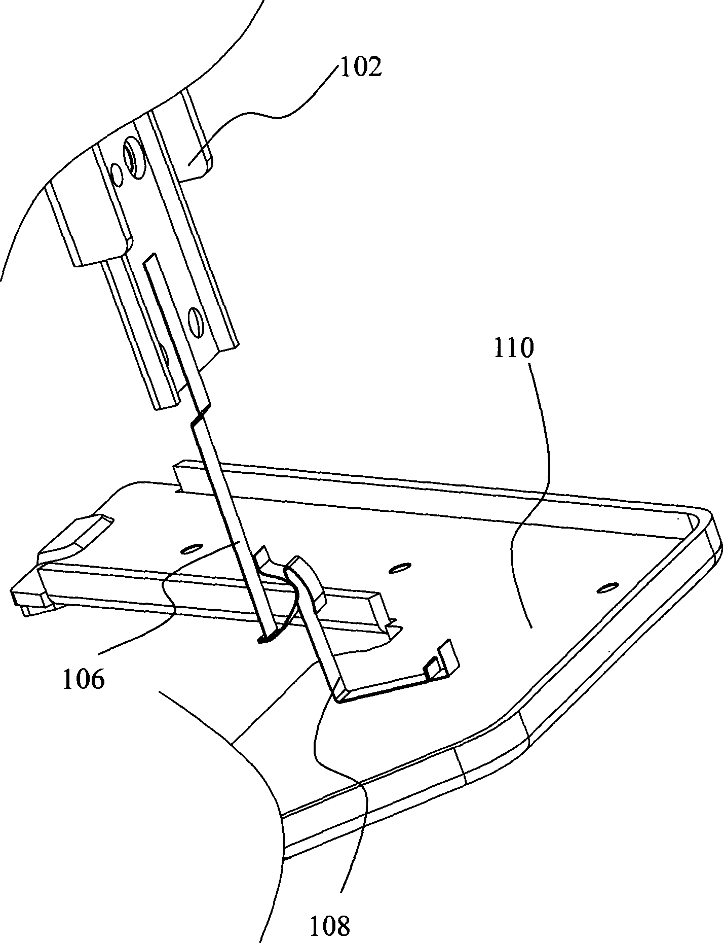
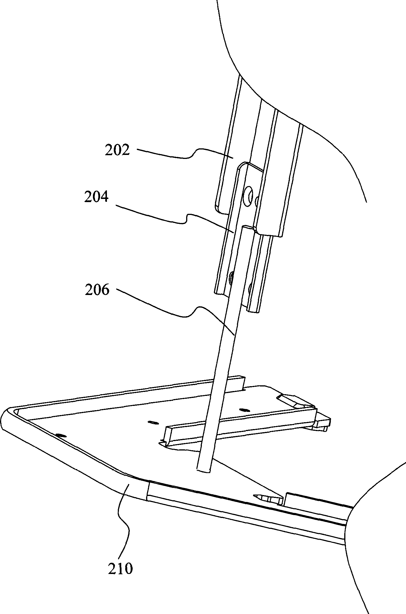
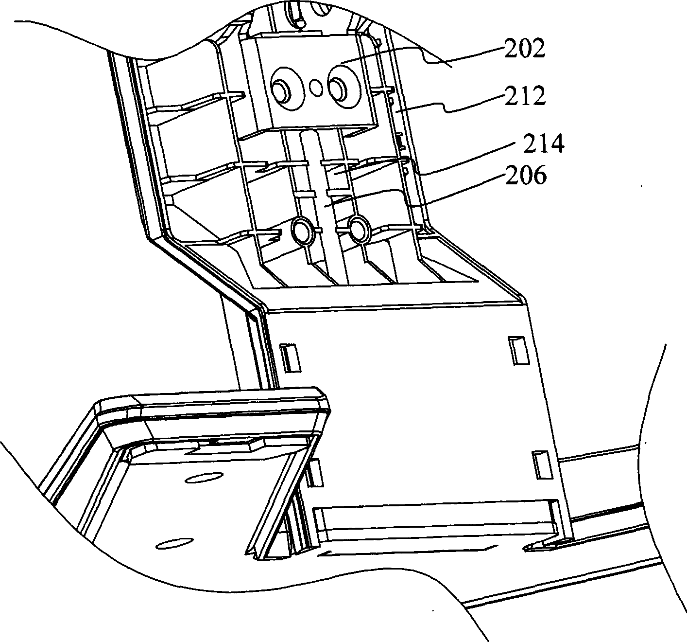
[0019] See figure 2 , figure 2 It is a schematic diagram of the grounding mechanism of the electronic device. The grounding mechanism of the present invention includes: an electrical node connector 202 , a conducting member 204 , a conductive rubber 206 and a base 210 . The electrical node connector 202, the via 204, and the base 210 are all conductive. In this embodiment, the electrical node connector 202 , the conducting member 204 and the base 210 are all made of ferrous material. The electrical node connector 202 is connected to the electrical node in the electronic device that needs to be grounded, and the electrical node that needs to be grounded is omitted in the figure. The electrical node connecting piece 202 is connected to the conducting piece 204 for conduction. The conductive rubber 206 is connected to the conductive member 204 , and the base 210 is connected to the conductive rubber 206 . In this way, through the connection function of the conductive rubbe...


PUM


Abstract

A grounding mechanism of electronic equipment comprises a shell body, an electric node connecter arranged in the shell body, and a base. The grounding mechanism is characterized in that the electric node connecter is electrically connected with the base through a conductive rubber so as to realize the grounding. In the invention, the electric node connecter is communicated with the base through the conductive rubber, so as to realize the grounding, and the conductive rubber is not easy to become deformed, so that the invention not only improves the grounding quality of the electronic equipment but also requires not too much about the assembly, the package and the transportation of the electronic equipment, thus reducing the production cost.

Description

technical field [0001] The invention relates to a grounding mechanism, in particular to a grounding structure of an electronic device using conductive rubber for grounding. Background technique [0002] Grounding is a very important item in the electrical field, because many electronic devices often need to be grounded for the following reasons: [0003] (1) Equipotentialization—assuming that there are two shells of instruments with different potentials, when someone accidentally touches the two instruments at the same time, there is obviously a risk of electric shock. Therefore, if all equipment can be properly grounded, the danger of potential differences can be greatly reduced. This situation is especially important in hospitals, because patients often use several electronic therapeutic devices at the same time, plus metal bed frames, bedside lamps, etc., which are more likely to cause conductive accidents due to potential differences. [0004] (2) Abnormal protection -...

Claims


Application Information

Patent Timeline
IPC IPC(8): H05K5/02H01R4/00H01R4/48H01R4/62
Inventor 洪志谦陈家让姜晓燕张巧将
Owner LITE ON OPTO TECH (CHANGZHOU) CO LTD
Why Eureka
Try Eureka