
Linear friction welding method

A linear friction welding and welding process technology, which is applied in the field of variable amplitude linear friction welding and variable frequency, can solve the problems of poor quality of welded joints, etc., and achieve the effects of prolonging service life, eliminating residual stress, and uniform high temperature range

Inactive Publication Date: 2009-02-18
NORTHWESTERN POLYTECHNICAL UNIV
View PDF0 Cites 11 Cited by
  • Summary
  • Abstract
  • Description
  • Claims
  • Application Information

AI Technical Summary

Problems solved by technology

[0004] In order to overcome the shortcomings of the poor quality of welded joints in the prior art, the present invention proposes a linear friction welding method, which can effectively improve the quality of welded joints by adopting the method of variable frequency and variable amplitude

Method used

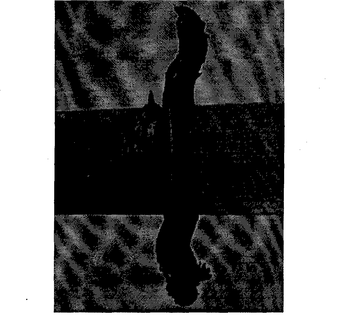
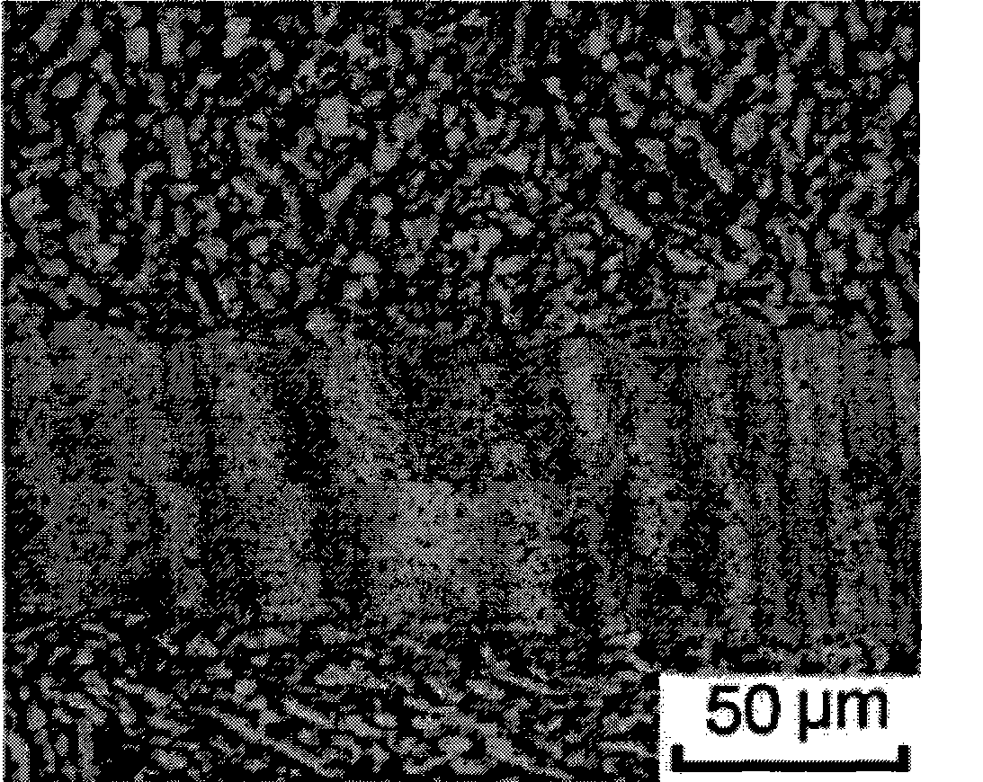
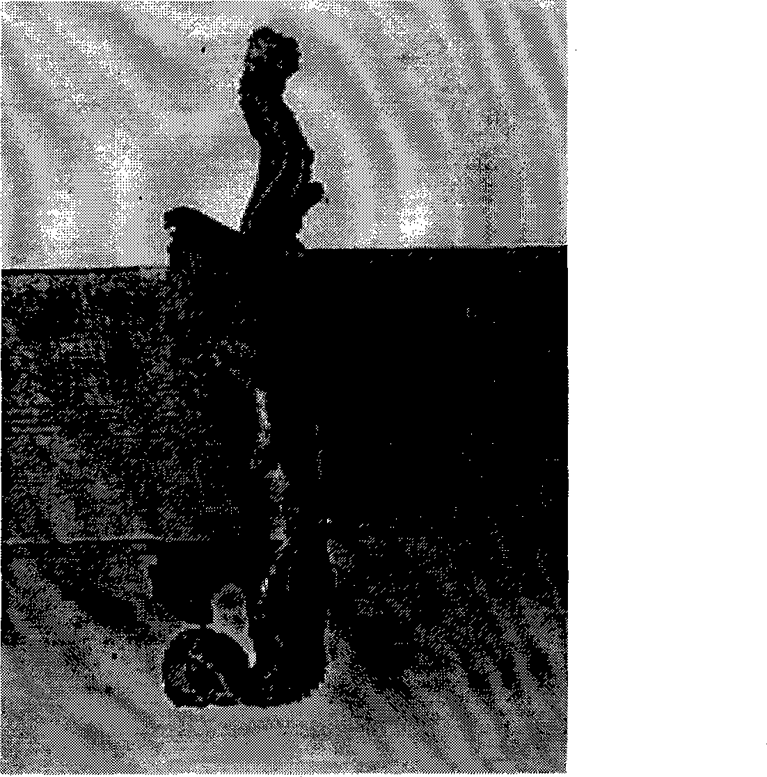

Image

  • Linear friction welding method
  • Linear friction welding method
  • Linear friction welding method

Examples


Embodiment 1

[0013] Embodiment 1: Utilize the method of the present invention to carry out the linear friction welding test of TC4 titanium alloy. The length of the welded test piece is 46mm, the welded section is 15mm×18mm, and it vibrates and rubs along the direction of the 18mm dimension during welding. The process parameters are: the vibration frequency increases linearly from 10Hz to 30Hz within 2 seconds at the beginning of the friction; then enters the friction stage with a constant frequency of 30Hz and a constant amplitude of 1.5mm for 2 seconds; then the amplitude gradually decreases from 1.5mm to 0. Friction pressure 20MPa, upsetting pressure 60MPa.

Embodiment 2

[0014] Embodiment 2: A linear friction welding test of No. 45 steel was carried out by using the method of the present invention. The length of the welded test piece is 46mm, the welded section is 20mm×60mm, and it vibrates and rubs along the 60mm dimension direction during welding. The process parameters are: the vibration frequency increases linearly from 20Hz to 60Hz within 3 seconds at the beginning of the friction; then enters the friction stage with a constant frequency of 60Hz and a constant amplitude of 2.0mm for 8 seconds; then the amplitude decreases linearly from 2.0mm to 0. Friction pressure 50MPa, upsetting pressure 100MPa.

Embodiment 3

[0015] Embodiment 3: A linear friction welding test of No. 45 steel was carried out by using the method of the present invention. The length of the welded test piece is 46mm, the welded section is 30mm×80mm, and it vibrates and rubs along the direction of 80mm dimension during welding. The process parameters are: the vibration frequency increases linearly from 30Hz to 90Hz within 4 seconds at the beginning of the friction; then enters the friction stage with a constant frequency of 90Hz and a constant amplitude of 3.0mm for 12 seconds; then the amplitude decreases linearly from 3.0mm to 0. Friction pressure 80MPa, upsetting pressure 160MPa.


PUM


Abstract

The invention discloses a linear friction welding method, which is characterized in that the method comprises the following steps: the amplitude of two weldments is preset as a constant amplitude, and the vibration frequency is increased to higher frequency from lower frequency at the early stage of friction; then a constant-frequency constant-amplitude friction stage is performed, and the vibration frequency and the amplitude are constant at this time; at the final stage of the friction, the amplitude is gradually reduced, and the welding is finished by applying upsetting pressure when the amplitude is gradually reduced to zero to lead the two weldments to return and align; and the friction pressure is constant during the whole welding process. The larger amplitude and the lower frequency at the early stage of the friction can perform effective mechanical cleaning and preheating to the friction interface; at the middle and late stage of the friction, the amplitude is gradually reduced to ensure that a high temperature interval of a joint is wider and evener, deformed metal can be fully restored and recrystallized, thereby eliminating the residual stress of the welding joint and improving the quality of the joint.

Description

technical field [0001] The invention relates to a friction welding method, in particular to a linear friction welding method with variable frequency and variable amplitude. Background technique [0002] The document "Impact Toughness and Fracture Characteristics of TC4 Titanium Alloy Linear Friction Welded Joint Ma Tiejun, Zhang Xuejun, Yang Siqian, Zhang Yong, Zhang Yunxia "Journal of Aeronautical Materials" No. 6, 2007, pages 40-44" discloses a linear friction welding method , the method adopts the constant frequency and constant amplitude welding process, that is, during the whole welding process, the frequency and amplitude remain constant, until the end of welding, the amplitude drops sharply from a constant value to 0, so that the two weldments are returned to the center, and at the same time Apply an upsetting force to complete the weld. The process parameters disclosed in the literature are: vibration frequency 15Hz, amplitude 3.8mm, friction pressure 17.9kN, upsett...

Claims


Application Information

Patent Timeline
IPC IPC(8): B23K20/12
Inventor 李文亚马铁军马宗耀张勇杨思乾
Owner NORTHWESTERN POLYTECHNICAL UNIV
Learn More