Improved labyrinth type air intake chamber structure

An air inlet chamber and labyrinth technology, applied in the field of the improved labyrinth air inlet chamber structure, can solve the problems of unqualified glass fiber reinforced plastic, easy to block pipes, unstable wind pressure in the fan room, etc., to achieve effective filtration and ensure normal operation. , the effect of stable wind pressure

Active Publication Date: 2009-02-18
无锡海达光能股份有限公司
View PDF0 Cites 1 Cited by
  • Summary
  • Abstract
  • Description
  • Claims
  • Application Information

AI Technical Summary

Problems solved by technology

[0002] In the past, when processing tempered glass, the fan of the tempering furnace was equipped with an air inlet chamber, and an air inlet was opened on the outer wall of the air inlet. The partition between the air inlet chamber and the fan chamber constituted the air outlet of the air inlet chamber. The filter screen, the air inlet is facing the air outlet of the air inlet room, and the air outlet is facing the fan suction port. Since the air is directly sucked into the fan from the air inlet of the air inlet room, the air suction volume of the fan will be affected by the outdoor natural environment, causing the fan room to be damaged. The air pressure inside is unstable, and the dust and debris in the air enter the equipment directly through the fan inlet when the air is sucked, which will easily block the pipe over time and lead to unqualified glass tempering

Method used


Image

  • Improved labyrinth type air intake chamber structure
  • Improved labyrinth type air intake chamber structure

Examples


Embodiment Construction

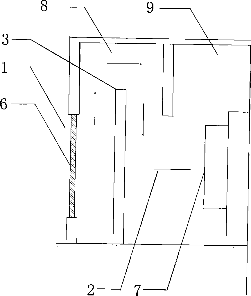
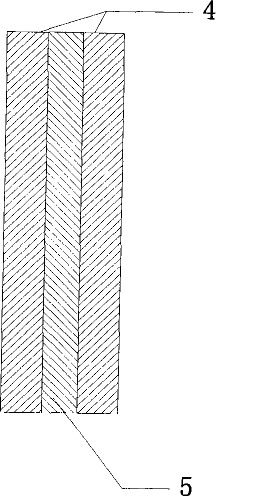
[0009] See figure 1 , figure 2 , a labyrinth-type air inlet chamber structure which includes an air inlet 1 and an air outlet 2, a filter screen 6 is installed on the air inlet 1, the air inlet 1 is facing the air outlet 2, and the air outlet 2 is facing the fan in the fan room The air suction port 7 is provided with a windshield wall 3 between the air inlet 1 and the air outlet 2, and the height of the windshield wall 3 is higher than that of the air inlet 1; Complete, fill the sound insulation cotton 5 between the double-layer hollow bricks 4.

[0010] When the fan is working, the wind enters from the air inlet 1, moves upward along the windshield wall 3, then moves horizontally to the right along the ceiling, then moves downward along the partition between the air inlet chamber 8 and the fan chamber 9, and finally is drawn by the air inlet of the fan. Inhalation, the entire air stroke is in the shape of a "several". After the air enters from the air inlet, the windshiel...


PUM


Abstract

The invention provides an improved labyrinth type air intake chamber structure which can guarantee a relative stable wind pressure in a fan house as well as effectively prevent dust and impurities in air from entering equipment through fan inlet during air draft. The air intake chamber structure comprises an air inlet and an air outlet; wherein, the air inlet is provided with a filter screen; the air inlet is opposite to the air outlet; and the air outlet is opposite to an air suction port of a fan in the fan house. The air intake chamber structure is characterized in that an air stopping wall is arranged between the air inlet and the air outlet.

Description

(1) Technical field [0001] The invention relates to the field of fan technology, in particular to an improved labyrinth-type air inlet chamber structure. (2) Background technology [0002] In the past, when processing tempered glass, the fan of the tempering furnace was equipped with an air inlet chamber, and an air inlet was opened on the outer wall of the air inlet. The partition between the air inlet chamber and the fan chamber constituted the air outlet of the air inlet chamber. The filter screen, the air inlet is facing the air outlet of the air inlet room, and the air outlet is facing the fan suction port. Since the air is directly sucked into the fan from the air inlet of the air inlet room, the air suction volume of the fan will be affected by the outdoor natural environment, resulting in the failure of the fan room. The wind pressure inside is unstable, and the dust and sundries in the air enter the equipment directly through the fan inlet when the air is sucked, wh...

Claims


Application Information

Patent Timeline
Patent Type & Authority Applications(China)
IPC IPC(8): C03B27/04
Inventor 冯建敏
Owner 无锡海达光能股份有限公司
Why Eureka
Try Eureka