
Rail noise controller

A controller and noise technology, applied in tracks, roads, buildings, etc., can solve the problems of difficult replacement of intermediate layer damping materials, insufficient vibration and noise reduction effects, etc., and achieve the effects of low cost, convenient installation, and convenient installation and maintenance.

Inactive Publication Date: 2009-02-18
BEIJING JIAOTONG UNIV
View PDF1 Cites 18 Cited by
  • Summary
  • Abstract
  • Description
  • Claims
  • Application Information

AI Technical Summary

Problems solved by technology

The patent application number is 200610023902.2, the examination and approval announcement number is 1807756, and the patent name is "dynamic vibration absorption multi-layer restraint damping rail muffler". The Chinese invention patent application discloses a multi-layer restraint damping rail muffler. Multi-layer constrained damping is pasted on the waist and rail wings, and the multi-layer constrained damping is high elastic energy consumption material layer, first mass layer, first damping layer, first constrained layer, second damping layer, second constrained layer from inside to outside , the third damping layer, the third constraining layer and the protective layer. The disadvantages of this invention are: 1. Only paste multi-layer noise reduction damping on the rail waist and rail wing of the railway rail, and the noise suppression is not installed at the bottom of the rail equipment, so that the vibration and noise reduction effect of the invention is not perfect; 2. After the damping layer is aging, it is difficult to replace the damping material of the middle layer

Method used


Image

  • Rail noise controller
  • Rail noise controller
  • Rail noise controller

Examples


Embodiment Construction

[0015] The present invention will be further described below in conjunction with the accompanying drawings.

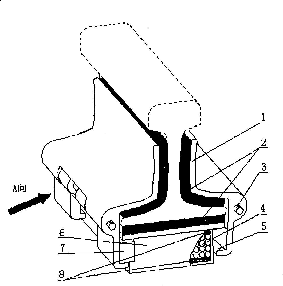
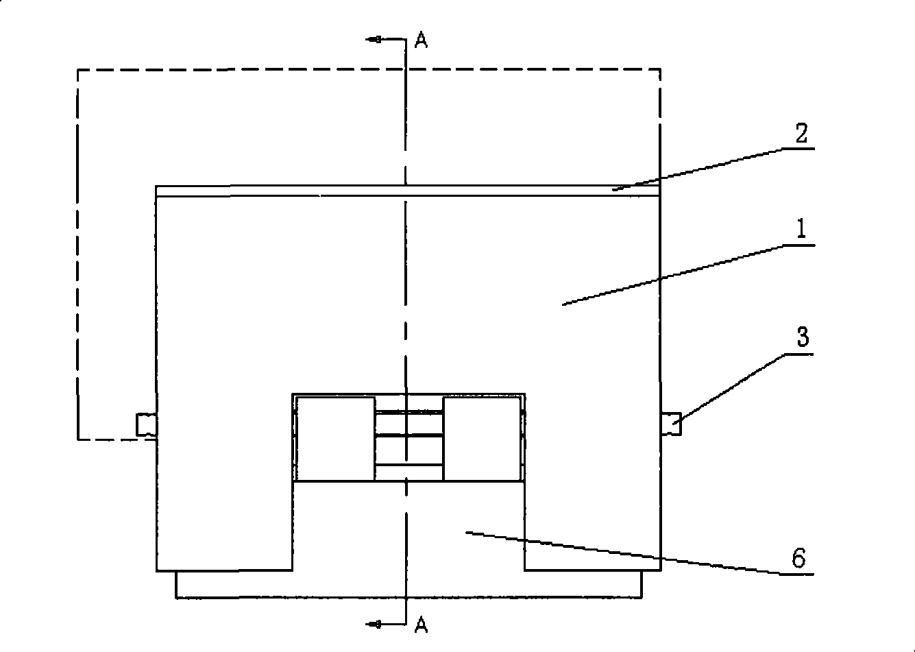
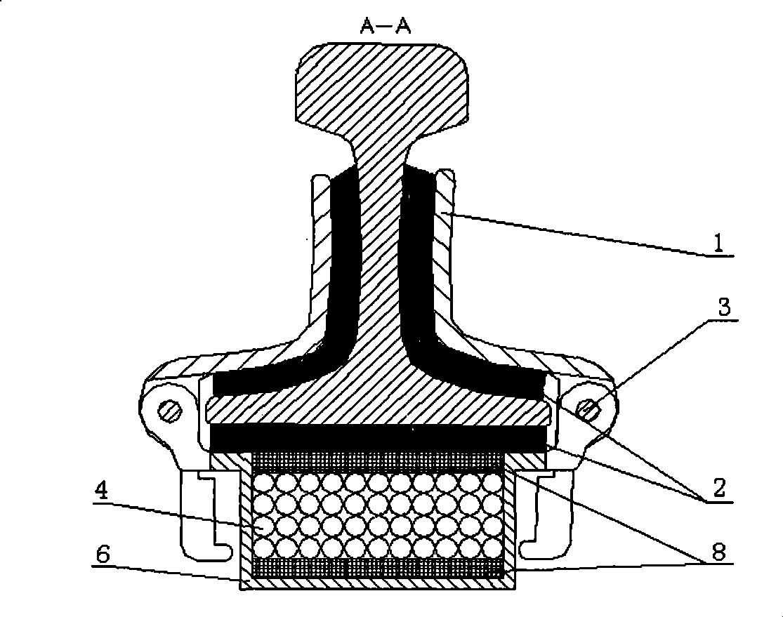
[0016] Such as figure 1 As shown, the damping layer 2 is respectively covered on the two side surfaces of the rail waist and the rail wing and the bottom surface of the rail. The damping layer 2 is made of high damping rubber. The damping layer 2 on the two sides of the rail waist and the rail wing The constrained layer member 1 is covered on the top, and the lower part of the constrained layer member 1 has two pin holes, and the upper side of the dynamic vibration absorber housing 6 has two pin holes, and the pin shaft 3 passes through the pin shaft holes to connect the constrained layer member 1 It is connected with the dynamic shock absorber shell 6. The clamping force between the constrained layer member 1 and the dynamic vibration absorber and the rail surface is implemented through the wedge block 7. The end of the curved lower arm of the constrained layer membe...


PUM


Abstract

The invention discloses a railway noise controller which is installed on a rail, belonging to noise control field. The noise controller comprises a restraint layer member, a damp layer, a pin roll, a mass block, a retainer pin, a dynamic vibration absorber shell, a wedge-shaped block and an elastic layer. The damp layer is installed at the waist, the flange and the bottom of the rail, and is fixed by the restraint layer member and the dynamic vibration absorber shell. The restraint layer member and the dynamic vibration absorber shell are connected through the pin roll, and the wedge-shaped block exerts clamp force to the restraint layer member and the dynamic vibration absorber shell. The dynamic vibration absorber shell of the mass block is installed at the bottom of the rail and the mass block is connected with the shell through the elastic layer. The railway noise controller effectively reduces noise of the rail in aspect of the noise source. The railway noise controller can be installed on the rail and requires no bond for adhibiting, and is low in cost and convenient to maintain. The restraint layer member, the pin roll, the mass block, the retainer pin, the dynamic vibration absorber shell and the wedge-shaped block can be used repeatedly, and the damp layer and the elastic layer are convenient to replace.

Description

technical field [0001] The invention relates to a rail traffic noise control device, in particular to a rail noise controller installed on rails. Background technique [0002] At present, the prevention and control of rail transit train running noise mainly adopts noise reduction measures such as sound barriers and sound insulation windows, and carries out noise prevention and control from the transmission route. However, the construction cost of the sound barrier is high and the cycle is long, which affects the maintenance of the line by the construction workers, and the noise reduction effect of the sound barrier is also affected by the distance from the track to the barrier, which is difficult to meet the application requirements under various environmental conditions. [0003] As a new track noise control technology for track noise control, track noise controller can control train running noise from the perspective of sound source. The patent application number is 20061...

Claims


Application Information

Patent Timeline
Patent Type & Authority Applications(China)
IPC IPC(8): E01B19/00
Inventor 宋雷鸣张新华
Owner BEIJING JIAOTONG UNIV
Learn More