Impeller structure of ventilator

A technology of blower and impeller, applied in the field of impeller structure of blower, can solve the problems of increasing installation cost, time, money waste, and long time for re-installation and calibration, and achieves the best stability and avoids shaking or noise.

Inactive Publication Date: 2009-02-18
陈耀干
View PDF3 Cites 18 Cited by
  • Summary
  • Abstract
  • Description
  • Claims
  • Application Information

AI Technical Summary

Problems solved by technology

[0002] According to the axial flow blower, it is a general prior art in the field of air conditioning, and the structure of the blower generally has an asymmetrical design for the blades of the impeller, so that the impeller has an air supply effect when it is rotating forward, and it does not have an air supply effect when it is reversed. The assembly structure of the blower is designed to correspond to each other in the fixed part of the blade and the hub body, and the cone-shaped appearance is matched by male and female. It takes a long time to correct the angular position of the blades one by one when assembling the blades and the hub body. And the balance, stability and consistency after assembly need to be corrected again, if the combination is not firm, it will cause the risk of blade detachment; in the actual environment such as a tunnel, consider the direction of vehicle travel and exhaust direction, and set up a single air supply Direction of the existing axial-flow blower, or consider climate and environmental factors in different seasons to produce different directions of wind direction, and consider different time periods such as peak or non-peak hours to produce different traffic flow directions, for a blower with only a single air supply direction , the exhaust effect produced is not good, which will increase the installation cost and relatively increase the operating cost; and after the existing axial flow fan has been used for a long time, if it needs to renew or correct the blades, it will be reinstalled due to the wear of the blades. It takes a long time for calibration and correction or the risk of falling off occurs during use, resulting in time, money waste and danger; and the present invention is designed to improve the shortcomings of the prior art

Method used


Image

  • Impeller structure of ventilator
  • Impeller structure of ventilator
  • Impeller structure of ventilator

Examples


Embodiment Construction

[0013] In order to make the present invention clear and detailed, the preferred embodiments are enumerated hereby in conjunction with the following illustrations, and the structure and technical characteristics of the present invention are described in detail as follows:

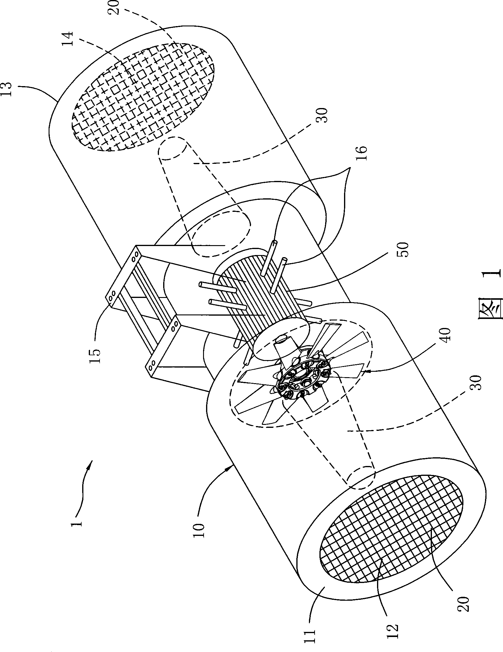
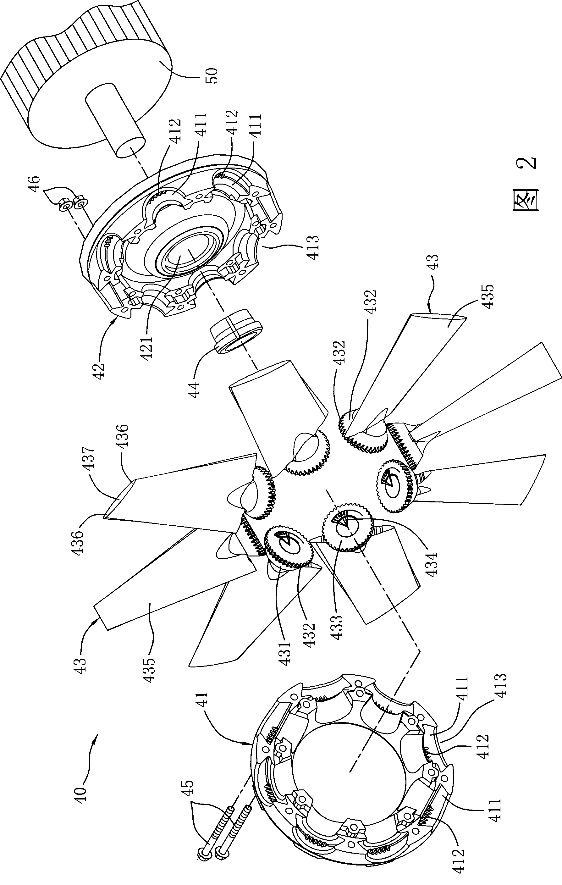
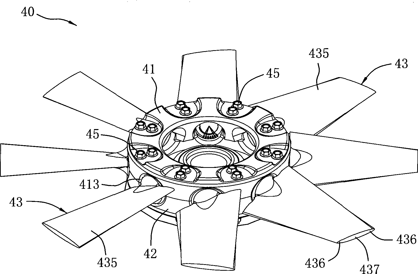
[0014] Please refer to Figure 1 to Figure 4 As shown, the air blower 1 of the present invention includes a cylindrical outer box 10. The outer box 10 is a double-layer shell structure with inner and outer layers, and can use galvanized steel plate and galvanized punched steel plate or the like It is made of board, and the sound-absorbing material can be filled between the outer layer and the inner layer. The sound-absorbing material can be made of cotton material; An air outlet 14 is arranged on the top; in addition, at least one above bracket 15 can be arranged at an appropriate place outside the outer box 10, so that the air blower 1 can be suspended for use through the bracket 15, such as suspended on th...


PUM


Abstract

The invention provides the impeller structure of a blower; the blower includes a cylindrical outer case; a wind inlet and a wind outlet are respectively arranged on both ends of the cylindrical outer case; a motor is adopted to drive the vanes of an impeller to rotate inside the outer case; the vanes rotate to drive the air to enter the wind inlet and exhaust from the wind outlet; the impeller structure comprises a hub base composed of an upper hub body and a lower hub body; a plurality of corresponding concave grooves are respectively arranged in the interiors of the upper and lower hub bodies with equal angles; tooth-shaped parts and a plurality of vanes are arranged on the inner lateral surfaces of the concave grooves respectively; each vane is provided with a truncated cone shaped fixation part; the fixation parts are clamped in the corresponding concave grooves in the interiors of the upper and lower hub bodies; the conical hemlines of the fixation part are provided with tooth-shaped peripheries meshed with the tooth-shaped parts of the upper and lower hub bodies; based on the structure, the vanes clamped in the hub base can have good firmness, so as to avoid the swaying or noise and facilitate the assembly of the vanes or the adjustment operation of the angles.

Description

technical field [0001] The present invention relates to an impeller structure of a blower, especially an annular tooth shape around the conical bottom edge of the truncated conical fixing part of the blade of the impeller, and the annular tooth Shaped shape is correspondingly meshed with the teeth in the grooves of the upper and lower shells, so that the fixed parts can be tightly fitted in the grooves of the upper and lower hubs, so as to improve the stability of the blades Consistent impeller structure. Background technique [0002] According to the axial flow blower, it is a general prior art in the field of air conditioning, and the structure of the blower generally has an asymmetrical design for the blades of the impeller, so that the impeller has an air supply effect when it is rotating forward, and it does not have an air supply effect when it is reversed. The assembly structure of the blower is designed to correspond to each other in the fixed part of the blade and ...

Claims


Application Information

Patent Timeline
Patent Type & Authority Applications(China)
IPC IPC(8): F04D29/38F04D29/34
Inventor 陈耀乾
Owner 陈耀干
Why Eureka
Try Eureka