Vacuum pump

A vacuum pump and vacuum technology, applied in the direction of pumps, rotary piston pumps, rotary piston machines, etc., can solve the problems of complex design, high relative speed, etc., and achieve the effect of long service life, high suction performance, and low-cost structure

Inactive Publication Date: 2009-02-18
OERLIKON LEYBOLD VACUUM
View PDF1 Cites 3 Cited by
  • Summary
  • Abstract
  • Description
  • Claims
  • Application Information

AI Technical Summary

Problems solved by technology

[0003] It is known, for example, that rotary slide valve vacuum pumps of the dry-running type have the disadvantage of high relative velocities on the friction componen

Method used


Image

  • Vacuum pump
  • Vacuum pump
  • Vacuum pump

Examples


Embodiment Construction

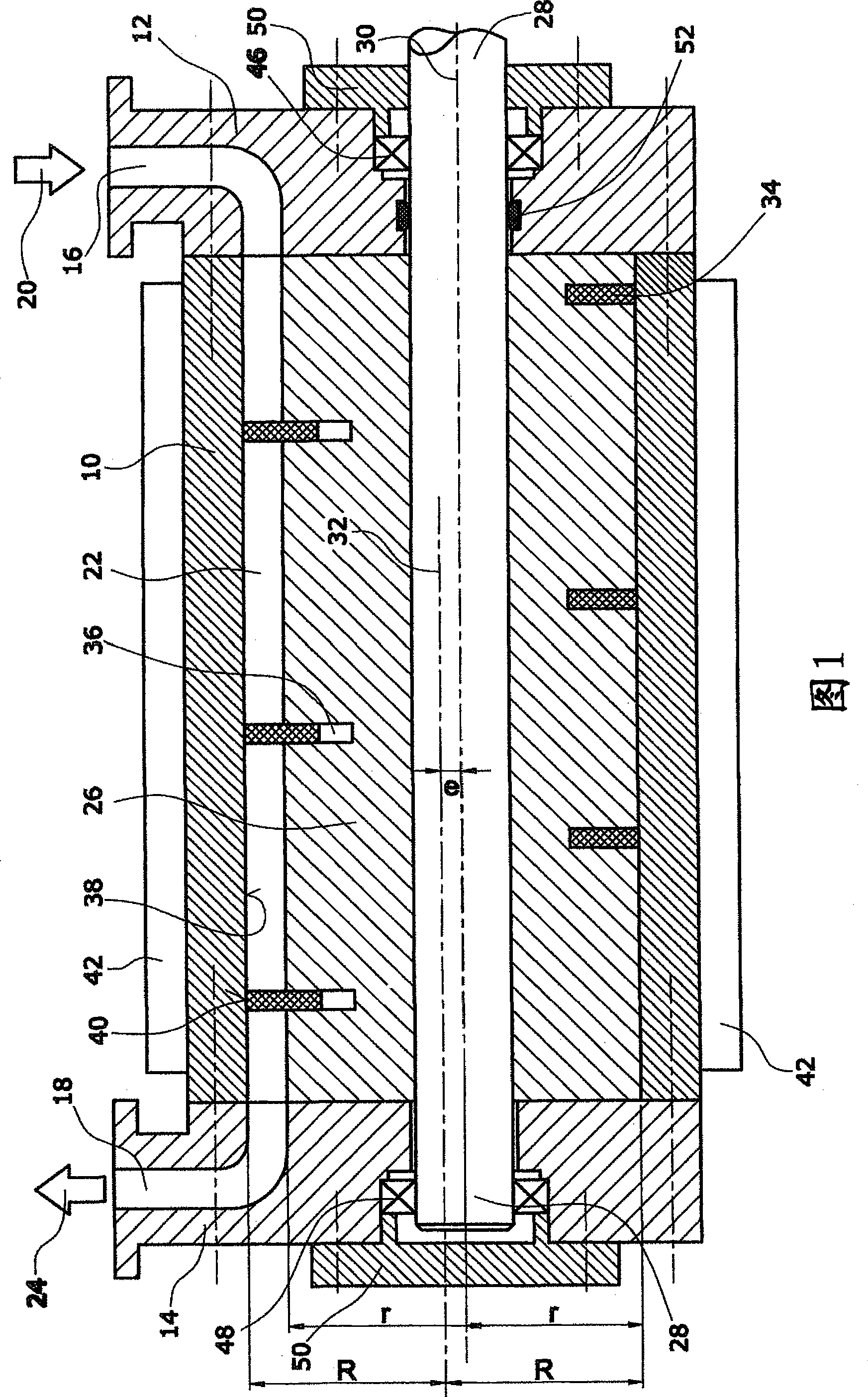
[0027]According to a first preferred embodiment of the invention ( FIG. 1 ), the vacuum pump comprises a stationary housing 10 . The housing 10 is closed by an inlet cover 12 and an outlet cover 14 . The inlet cover 12 includes an inlet 16 connected to the space to be evacuated. The outlet cover 14 is provided with a connection 18 for venting the gas drawn from the space to be evacuated. In this way, gas can move from the space to be evacuated via the inlet 16 into the cylindrical interior space 22 of the housing 10 in the direction of arrow 20 and via said outlet connection 18 provided in the outlet cover 14 in the direction of arrow 24 Leave the interior space.

[0028] A cylindrical propeller 26 is positioned inside the cylindrical space 22 . The propeller 26 is arranged concentrically with the shaft 28 . Thus, the central axis 30 of the propeller corresponds to the central axis of the shaft 28 . The shaft 28 is arranged eccentrically within the cylindrical inner space...


PUM


Abstract

A vacuum pump for producing a vacuum in a space which is to be evacuated has a housing (10) having a cylindrical inner space (22). An expeller (26) is arranged eccentrically in the inner space (22). A helical sealing element (34) is provided between the expeller (26) and an inner wall (38) of the housing (10) for forming at least one crescent-shaped conveying space. The housing (10) or the expeller (26) are connected to a drive device (44) for producing a relative rotary movement between the housing (10) and the expeller (26). According to the invention, the vacuum pump is configured as a dry-running vacuum pump.

Description

technical field [0001] The invention relates to a vacuum pump for generating vacuum in a space. Background technique [0002] Vacuum pumps are used to evacuate spaces in which processes are to be carried out which are largely affected by, inter alia, particles. Such processing takes place especially in semiconductor production, gas deposition processing and chemical processing. Dry-running pumps are required in order to prevent the penetration of lubricating substances from the vacuum pump into the space to be evacuated. [0003] It is known, for example, that rotary slide valve vacuum pumps of the dry-running type have the disadvantage that high relative velocities occur on the friction components, ie between the slide and the inner wall of the pump chamber. Since high relative speeds are unavoidable for the permissible volume flow, the service life of rotary slide valve vacuum pumps (rotary slide valve vacuum pumps) is relatively short. [0004] Another variant of the d...

Claims


Application Information

Patent Timeline
IPC IPC(8): F04C18/107
CPCF04C18/107F05C2201/0442
Inventor 托马斯·德赖费特汉斯-罗胡斯·格罗斯
Owner OERLIKON LEYBOLD VACUUM
Why Eureka
Try Eureka