

Suction device of dust collector
A technology of inhalation device and vacuum cleaner, applied in the direction of suction nozzle, etc., can solve the problem of difficult inhalation of foreign substances, etc., and achieve the effect of improving inhalation performance
- Summary
- Abstract
- Description
- Claims
- Application Information
AI Technical Summary
Problems solved by technology
Method used
Image

Examples
Embodiment Construction
[0027] The suction device of the vacuum cleaner of the present invention will be described in detail below with reference to the drawings and embodiments. In the process of describing the embodiments of the present invention, the same names and symbols are used for the same structures as those of the prior art.
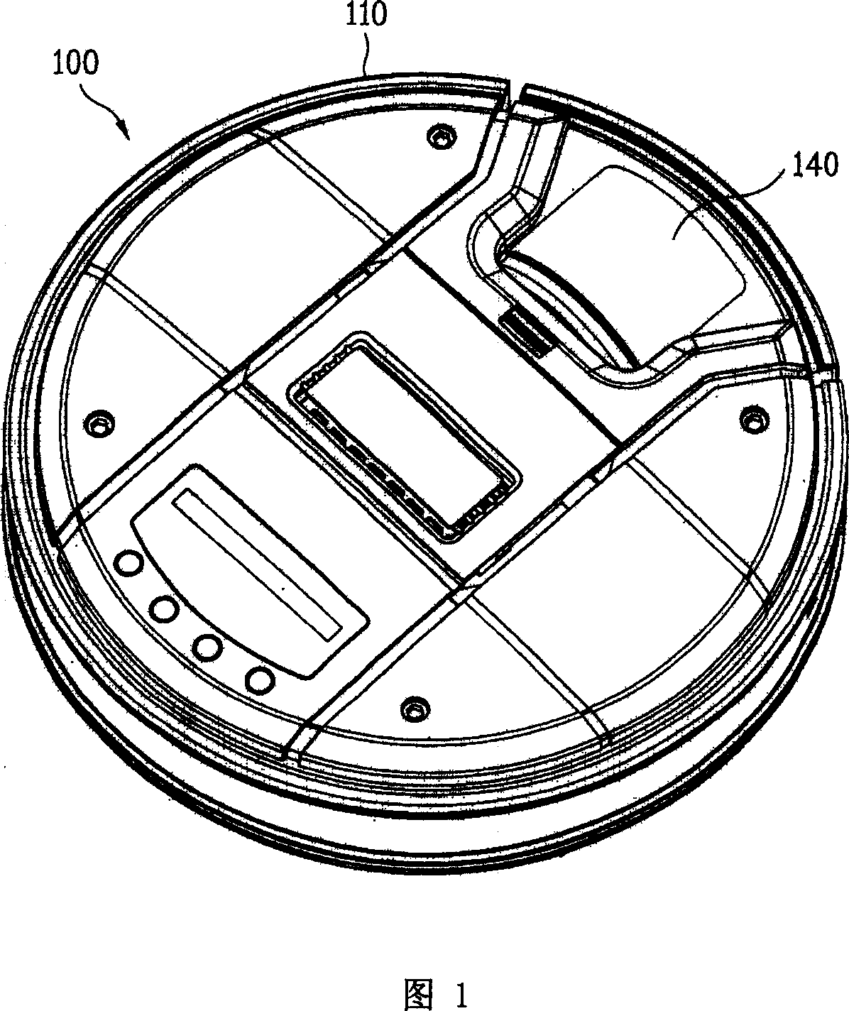
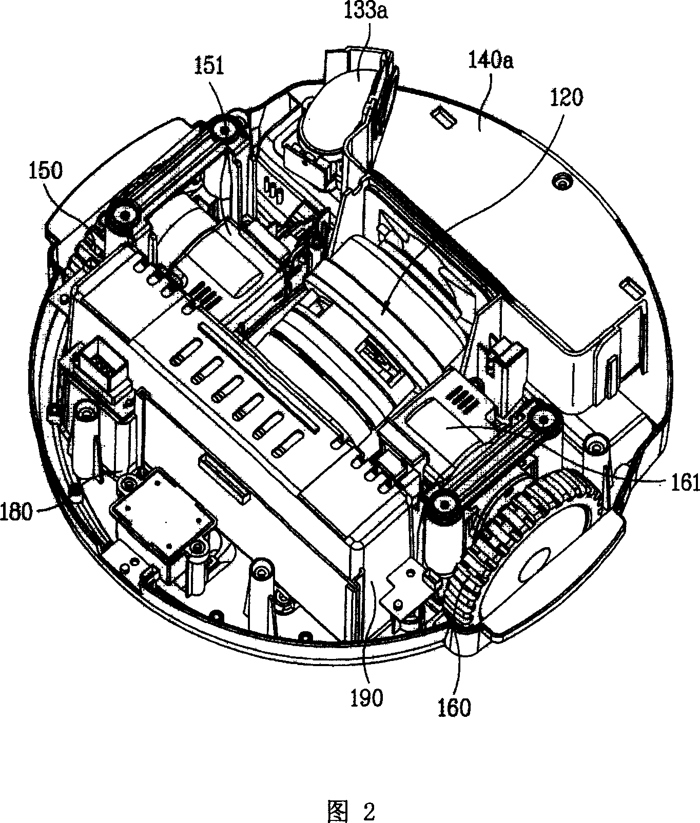
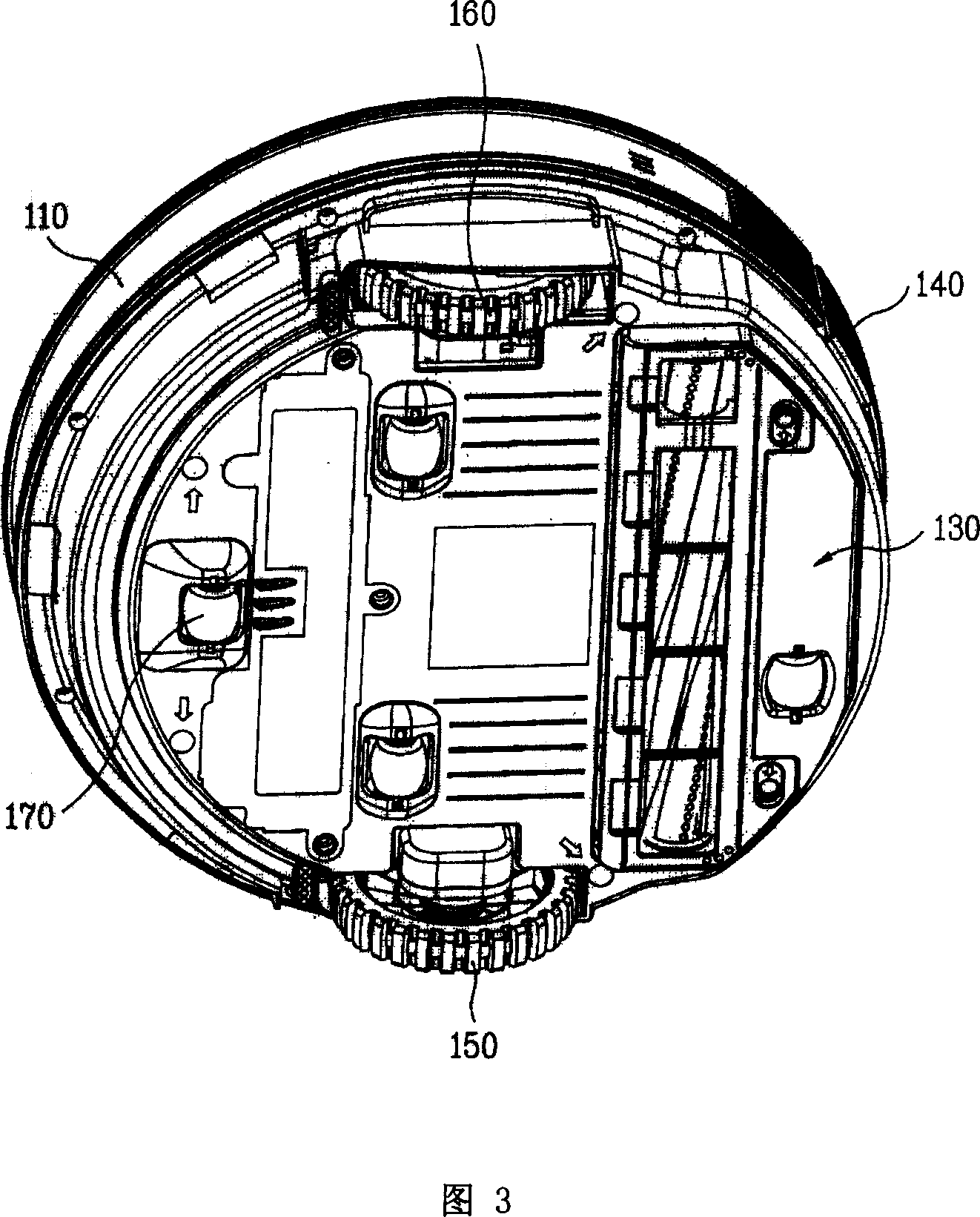
[0028] As shown in Figures 1-3, the automatic vacuum cleaner 100 includes a vacuum cleaner body 110 forming an appearance, an air suction assembly 120 located inside the vacuum cleaner body 110, a suction device 130 for sucking dust on the ground driven by the air suction assembly 120, and a collection suction device. 130 is a dust collector 140 that sucks foreign matter in the air.
[0029] The vacuum cleaner body 110 of the automatic vacuum cleaner 100 has a cylindrical shape with a height smaller than a diameter, that is, a flat cylindrical shape. The interior of the vacuum cleaner body 110 is provided with an air suction assembly 120 , a suction device 130 and a d...
PUM
 Abstract
Description
Claims
Application Information