Electric tools

A technology of electric tools and bridge circuits, applied in the field of electric tools, can solve the problems of excessive locking current, power supply voltage drop, large starting current, etc., and achieve the effect of expanding the speed range and suppressing the voltage drop.

Inactive Publication Date: 2009-02-25
MAKITA CORP
View PDF2 Cites 38 Cited by
  • Summary
  • Abstract
  • Description
  • Claims
  • Application Information

AI Technical Summary

Problems solved by technology

Furthermore, the starting current flowing through the DC motor is at its maximum at this time, so the power supply voltage drops due to the starting current between the start of driving the DC motor and the start of normal rotation of the DC motor.
[0011] Therefore, in an electric tool, if the DC motor lock determination is performed based on the power supply voltage, the lock determination cannot be normally performed immediatel...

Method used


Image

  • Electric tools
  • Electric tools
  • Electric tools

Examples


Embodiment Construction

[0041] Embodiments of the present invention will be described below based on the drawings.

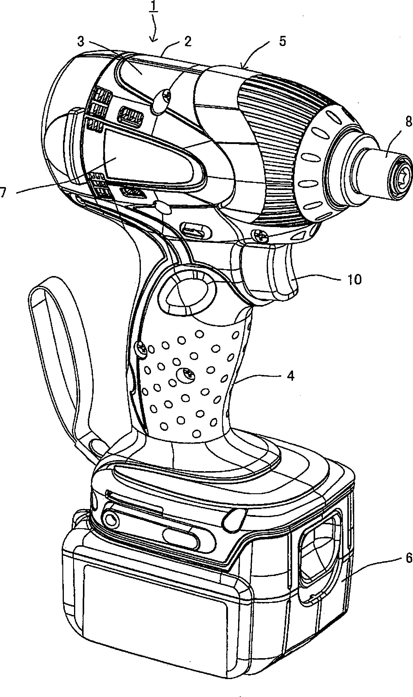
[0042] figure 1 It is a perspective view showing the appearance of the cordless impact driver 1 to which the embodiment of the present invention is applied.

[0043]The rechargeable impact driver 1 of this embodiment includes the following structure: a main body casing 5, which is assembled from the casings 2 and 3 divided in the left and right sides, and a handle part 4 is extended below; a battery pack 6, which is disassembled. It is freely attached to the lower end of the handle part 4 of the main body case 5 .

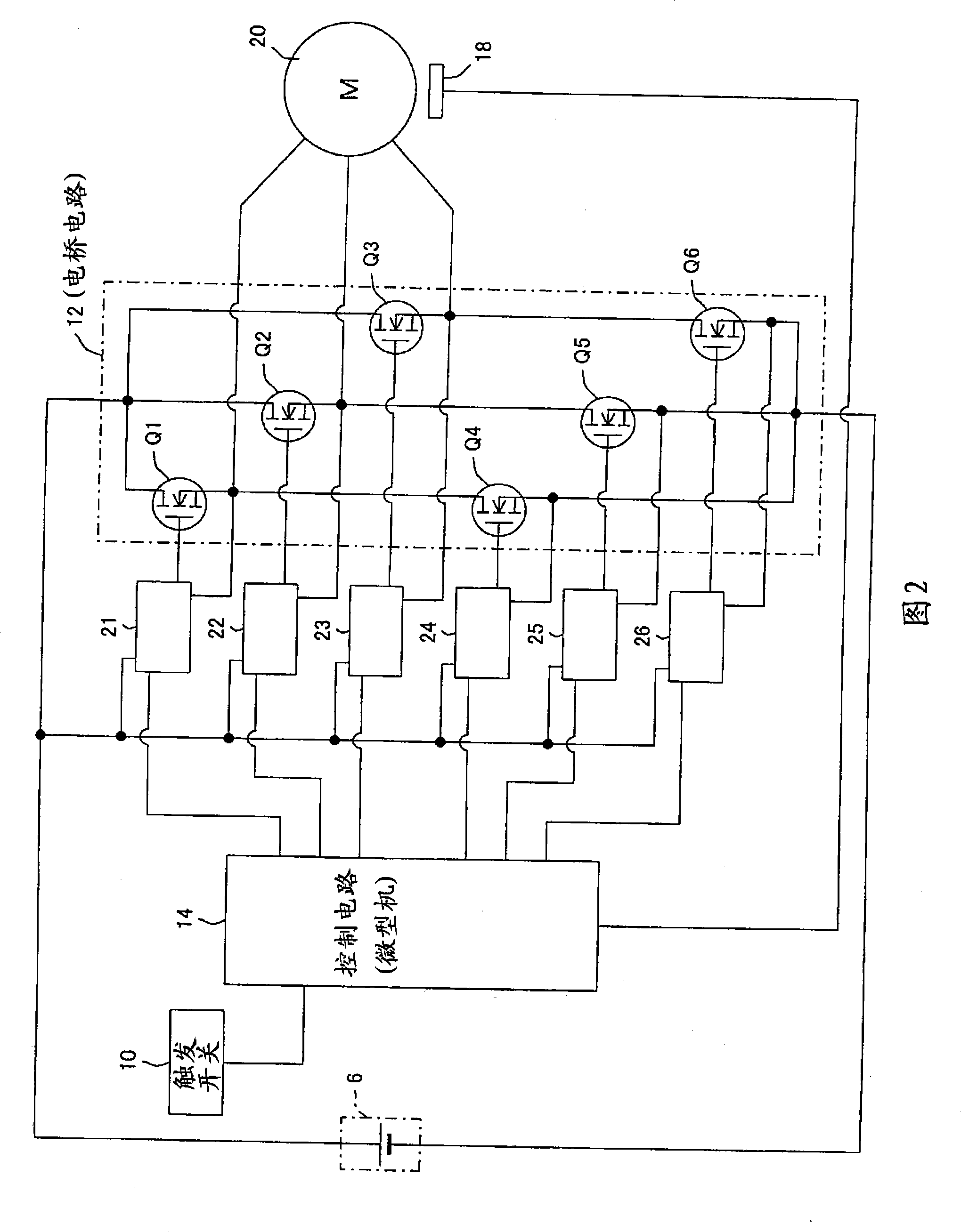
[0044] In addition, the rear of the main body casing 5 ( figure 1 on the left side of the cordless impact driver 1 is the motor housing part 7 that houses the DC motor 20 (see FIG. 2 ), which is the power source of the cordless impact driver 1, and the speed reduction mechanism is housed in the front of the motor housing part 7. and hitting mechanism.

[0045] In additi...


PUM


Abstract

The invention discloses an electric power tool controlling the rotation of a dc motor as a power supply on basis of an operation amount of a trigger switch capable of suppressing a starting current flowed when the motor drive is started. A driving duty ratio for PWM controlling the dc motor is set a starting duty ratio from the time of operating the trigger switch (t0) till the operation duration time (an on time) reaches 20ms (t1), then the dc motor is started. Thereafter when the on time is over 20ms, the driving duty ratio is set 50% till the on time reaches 30ms (t2), then the driving duty ratio is set 80% till the on time reaches 40ms (t3). Moreover, the driving duty ratio is set according to the operation amount of the trigger switch (10). The result is that the dc motor is increased in a stepwise manner during the period from the driving on until the start-up time (40ms) capable of suppressing the driving current and preventing the power voltage from descending.

Description

technical field [0001] The present invention relates to an electric tool that includes a DC motor as a power source and controls the rotation of the motor according to the operation amount of a trigger switch. Background technique [0002] Conventionally, in such electric tools, as a drive circuit of a DC motor, a bridge circuit (in other words, an inverter circuit) is provided between each terminal of the DC motor and the positive and negative terminals of the DC power supply (battery). The switching elements (high-side switch and low-side switch) constitute. [0003] Also, when the user operates the trigger switch, the control circuit finds the driving duty ratio for PWM control of the DC motor based on the amount of operation, and turns on / off the bridge circuit in accordance with the driving duty ratio. The switching element inside controls the rotation of the DC motor. [0004] In addition, in an electric tool, when the DC motor as a power source is driven, if the DC ...

Claims


Application Information

Patent Timeline
IPC IPC(8): B25F5/00
CPCH02P6/08B25F5/00
Inventor 松永隆山本浩克草川卓也
Owner MAKITA CORP
Why Eureka
Try Eureka