Combined structure of electromagnetic switch and relay and start-stop motor using structure

An electromagnetic switch and relay technology, applied in the direction of structural connection, circuit, electrical components, etc., can solve the problem of increasing the short circuit between the connecting wire and the automobile engine, the difficulty of maintaining the connecting wire, and reducing the reliability and effect of the current limiting resistor to suppress the peak starting current of the motor. And other issues

Active Publication Date: 2015-06-17
GAC COMPONENT CO LTD +1
View PDF8 Cites 0 Cited by
  • Summary
  • Abstract
  • Description
  • Claims
  • Application Information

AI Technical Summary

Problems solved by technology

[0006] First, because the electromagnetic switch K2 and the ICR relay K1 are all separated from the motor 25 and installed side by side in the automobile engine installation place, they take up a large space, which is not conducive to the miniaturization of the automobile engine and the operation of installation and maintenance;
[0007] Second, because the electromagnetic switch K2 and the ICR relay K1 are each of a single structure, the electromagnetic switch K2 and the ICR relay K1 need to be electrically connected with a connecting wire, and the connecting wire must also be wrapped with an insulating material, which increases the connection between the connecting wire and the car. risk of short circuits in the engine;
[0008] Third, due to the relatively short distance between the electromagnetic switch K2 and the ICR relay K1, their installation often requires special fixtures, which is not conducive to the simplification of the starter motor installation process, resulting in longer process time and increased process costs. The installation position of the machine on some models is extremely narrow, and it is extremely difficult to install the electromagnetic switch K2 and ICR relay K1 separately and replace the connecting wires;
[0009] Fourth, due to the split structure of the electromagnetic switch K2 and the ICR relay K1, the utilization rate of the components and materials of the electromagnetic switch K2 and the ICR relay K1 is reduced to a certain extent, resulting in a higher production cost of the start-stop motor;
[0010] Fifth, the cut-in / cut-out of the current-limiting resistor is controlled by the relay winding, which is susceptible to electromagnetic interference and causes deviations in the cut-in / cut-out of the current-limiting resistor, which reduces the reliability and effect of the current-limiting resistor in suppressing the peak starting current of the motor

Method used


Image

  • Combined structure of electromagnetic switch and relay and start-stop motor using structure
  • Combined structure of electromagnetic switch and relay and start-stop motor using structure
  • Combined structure of electromagnetic switch and relay and start-stop motor using structure

Examples


Embodiment 1

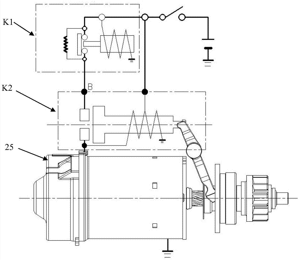
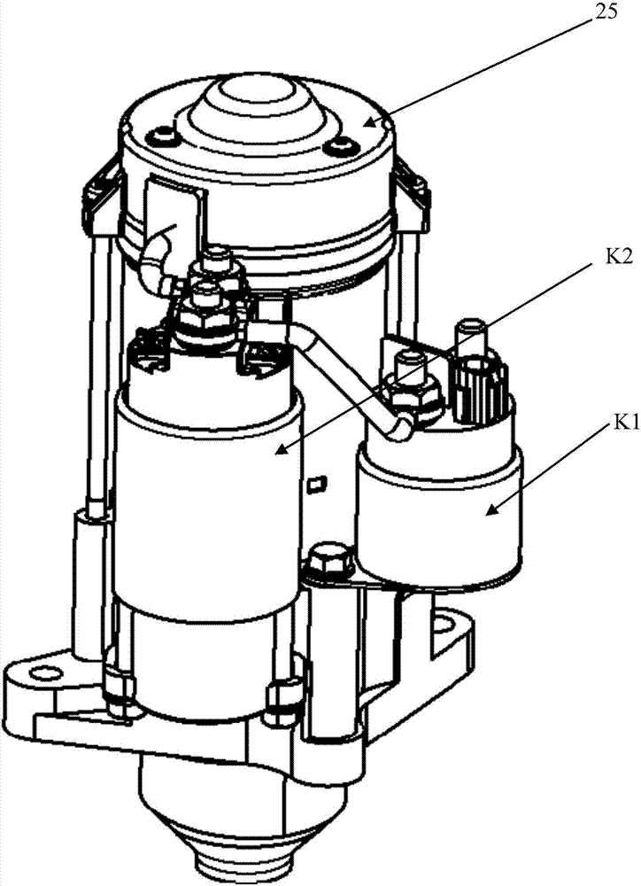
[0070] Such as Figure 4 to Figure 7-2 , Figure 11 to Figure 14 As shown, the integrated structure of the electromagnetic switch and relay in Embodiment 1 of the present invention includes a long cylindrical shell, an electromagnetic switch mechanism, a relay mechanism, a terminal block 26 , a controller 24 and a control terminal S. Wherein, the electromagnetic switch mechanism is installed in the bottom of the long shell, and the relay mechanism is positioned at the top of the electromagnetic switch mechanism in the long shell, that is, in the middle of the long shell, and the two are positioned at intervals by the terminal block 26; the long shell is composed of a cover body 22, a shell body 16 and inner housing 23; the electromagnetic switch mechanism includes a switch action assembly composed of switch winding 1, switch core 2, switch push rod 3, switch spring 4, switch dynamic and static contacts 5, 20 and output terminal M The relay mechanism includes a relay action as...

Embodiment 2

[0085] Such as Figure 4 , Figure 8-1 to Figure 14 As shown, the combined structure of the electromagnetic switch and the relay of the second embodiment of the present invention and the first embodiment and the start-stop motor applying the structure are basically the same, and their difference is that the rod head 18a of the connecting rod 18 of the second embodiment is " T" shape, the iron core end cover 8b is a bottom open cover body with an inner cavity adapted to the rod head 18a, and the cover body is composed of an upper part made of a magnetically permeable material and a lower part made of a non-magnetically permeable material. , the outer surface of the cover is covered with a thin layer of non-magnetic material, and the relay iron core 8a is fixedly connected to the bottom opening of the iron core end cover 8b. In addition, in the second embodiment, the I-shaped rubber pad 19b is used to replace the connecting rod spring 19 in the first embodiment. The working pri...


PUM


Abstract

The invention discloses a combined structure of an electromagnetic switch and a relay and a start-stop motor using the structure. The combined structure is characterized in that an outer shell of the switch and an outer shell of the relay are combined into a whole to form a long-barrel-shaped outer shell, an electromagnetic switch mechanism is installed on the lower portion of the long outer shell, a relay mechanism is located in the position, above the electromagnetic switch mechanism, in the long outer shell, the electromagnetic switch mechanism and the relay mechanism are positioned in a spaced mode through a wire holder, a connecting rod coaxial with a switch ejector rod and a relay ejector rod is further arranged, when a user starts to start a motor, the switch ejector rod is utilized to push the connecting rod and an relay iron core which are mutually attracted, the relay ejector rod is made to eject a relay movable contact spring to cut in a current limiting resistor, the connecting rod and the relay iron core lose the attracting force by cutting off power of a relay winding when the current limiting time is over, and therefore the relay ejector rod resets so that the current limiting resistor can be cut out. The combined structure can reduce the mounting space of the start-stop motor, reduce the short circuit risk of the motor and simplify production processes and has the advantages of being high in reliability and easy to implement.

Description

technical field [0001] The invention relates to an integrated structure of an electromagnetic switch and an ICR relay for a start-stop motor and a start-stop motor applying the structure. Background technique [0002] The start-stop motor, also known as the start-stop motor, is used to start the engine of the car. Existing conventional start-stop motors are composed of a motor and an electromagnetic switch. The contacts of the electromagnetic switch are connected in series on the main circuit of the motor to control the gain and loss of power of the motor. The output shaft of the motor is connected with a starter gear. When the ignition switch is turned on, the coil of the electromagnetic switch is energized and the contact of the electromagnetic switch is connected to connect the main circuit of the motor, and the motor is energized to run. On the other hand, the attraction force of the electromagnetic switch pushes the starter gear to mesh with the ring gear of the engine....

Claims


Application Information

Patent Timeline
Patent Type & Authority Patents(China)
IPC IPC(8): H01H89/00H02K11/00H02K11/20
Inventor 陈和平胡锡胜唐黎明吴鉴沛罗水根方振伟曹连德
Owner GAC COMPONENT CO LTD
Why Eureka
Try Eureka