Coiling framework, motor and method for coiling motor stator

A technology of winding skeleton and stator iron core, which is applied in the manufacture of motor generators, the shape/style/structure of winding conductors, electrical components, etc., and can solve problems such as affecting motor reliability, motor short-circuit, and motor burnout.

Active Publication Date: 2009-02-25
GREE ELECTRIC APPLIANCES INC +1
View PDF0 Cites 10 Cited by
  • Summary
  • Abstract
  • Description
  • Claims
  • Application Information

AI Technical Summary

Problems solved by technology

Once there is bare copper in the incoming and outgoing parts of the U-phase coil, the mutual contact between the incoming and outgoing parts will cause a short circuit in the motor phase, and even cause the motor to burn out, affecting the reliability of the motor's operation.

Method used


Image

  • Coiling framework, motor and method for coiling motor stator
  • Coiling framework, motor and method for coiling motor stator
  • Coiling framework, motor and method for coiling motor stator

Examples


Embodiment Construction

[0037] Embodiment of winding skeleton:

[0038] Referring to FIG. 5 , it is a front view of an embodiment of the winding bobbin of the present invention, in which coils of various phases are wound on the winding bobbin. In this embodiment, the winding frame 8 has an annular columnar frame made of insulating material, and a ring plate 82 extending outward along the axial direction of the frame body is provided on the outer edge of one end of the frame body. There are a plurality of bosses 831, 832, 833 distributed along the circumferential direction, the bosses extend outward along the axial direction of the frame body, and the number of bosses is equal to the number of magnetic poles of the stator core, and each boss is connected to a corresponding to the magnetic poles. For example, in this embodiment, the boss 831 corresponds to the U-phase magnetic pole, the boss 832 corresponds to the V-phase magnetic pole, and the boss 833 corresponds to the W-phase magnetic pole. Moreo...


PUM


Abstract

The invention provides a wire winding frame, an electric motor and a wire winding method of an electric motor stator. The wire winding frame is sleeved on a stator core provided with a plurality of magnetic pole groups and comprises a frame body, and a routing wire chase composed of a girth sheet and lug bosses is arranged at one end of the frame body, wherein, each lug boss is provided with a projection as well as an incoming line plane and an outgoing line plane which are arranged on two sides of the projection; height difference exists among the incoming line planes of the lug bosses on the magnetic pole groups; the height difference also exists among the outgoing line planes of the lug bosses on the magnetic pole groups. The wire winding method comprises the coiling step of the windings of the magnetic pole groups, wherein, the wire-routing parts which connect winding main-bodies are arranged in the routing wire chase in a mutually separate manner. The wire winding frame, the electric motor and the wire winding method of the electric motor stator can prevent the wire-routing parts of stator windings from contacting mutually, avoid the phase fault among the stator windings, and increase the reliability for the operation of the electric motor.

Description

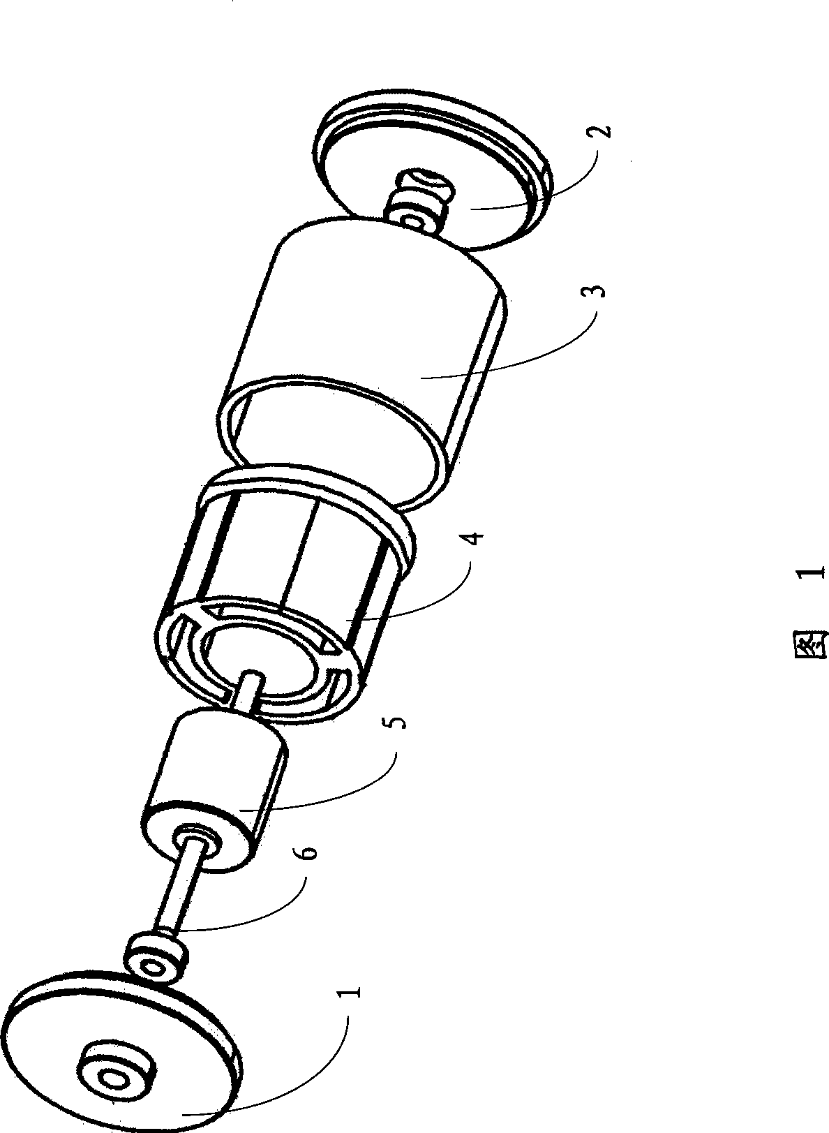
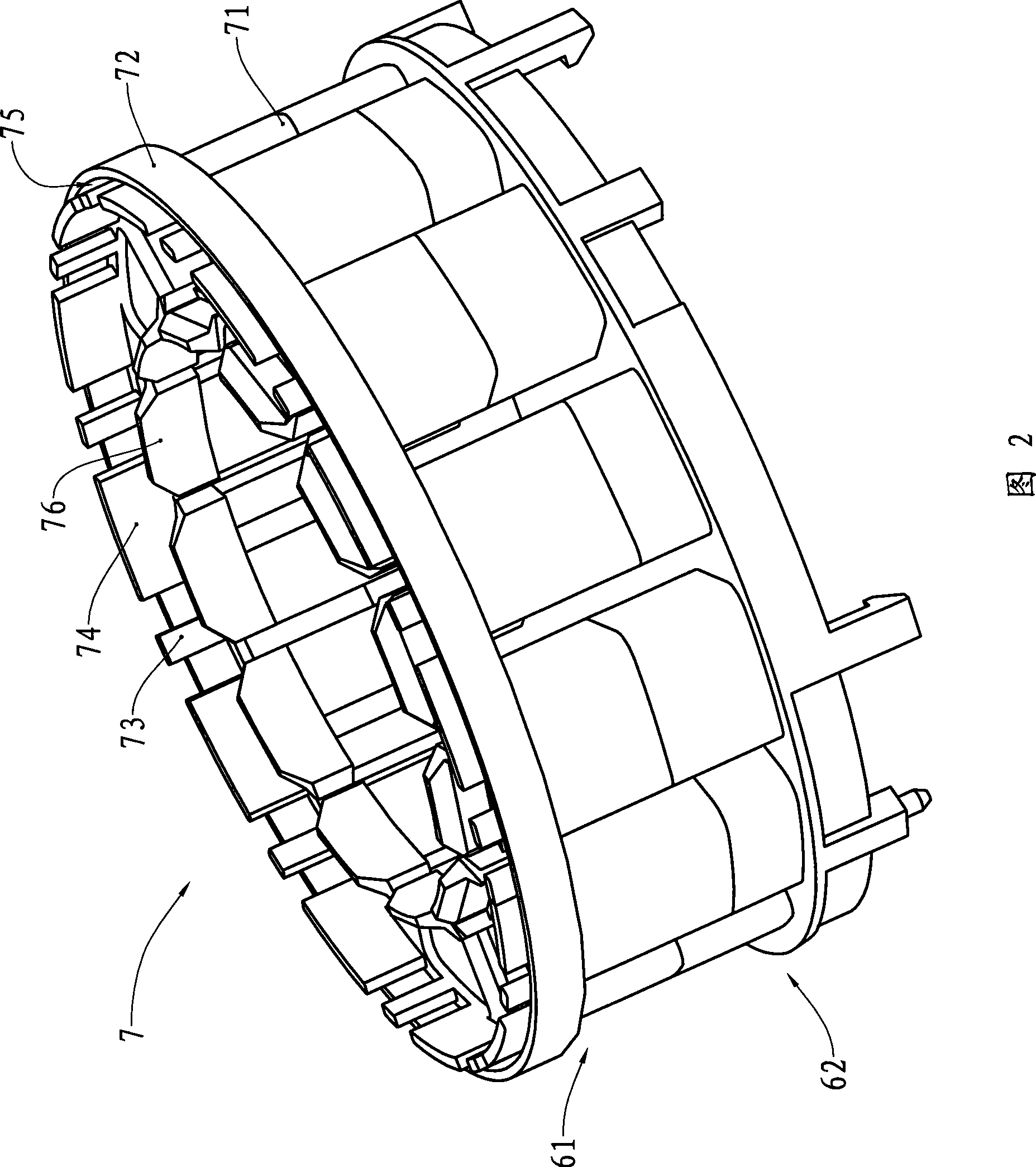
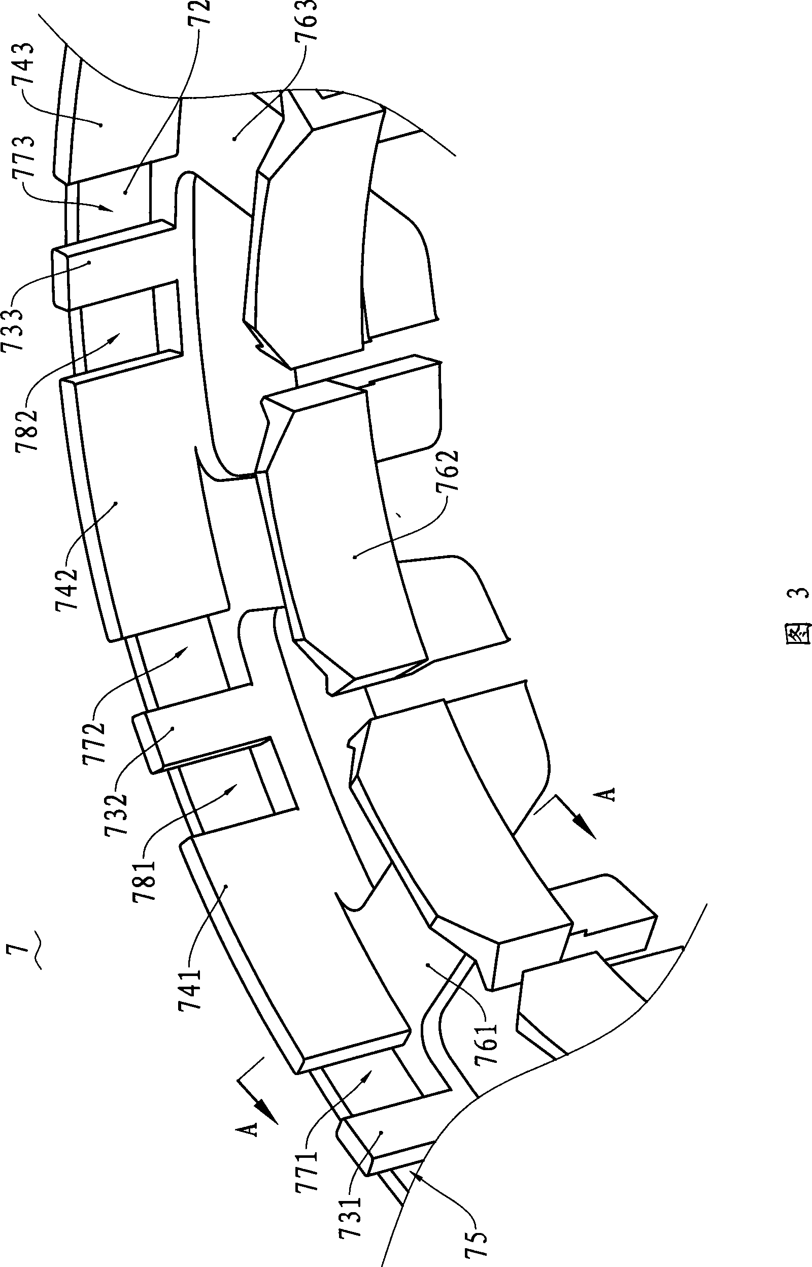
technical field [0001] The invention relates to a component of a motor winding, in particular to a winding frame set on the stator iron core of the motor stator, a motor using the winding frame, and a motor stator winding using the winding frame method. Background technique [0002] With the development of the national economy, motors have been widely used in various equipment, such as motors that drive fan blades, generators driven by wind or hydraulic power, etc. These are common motors. [0003] The structure of an existing motor is shown in Figure 1, which includes a front end cover 1, a rear end cover 2 and a housing 3. The housing 3 is an annular cylinder with a motor stator 4 inside, and a rotor 5 built into the motor stator 4. , The rotating shaft 6 of the rotor 5 is rotatably supported on the front end cover 1 and the rear end cover 2 . [0004] The existing motor stator 4 includes a stator iron core, which is mostly made of laminated silicon steel sheet materials...

Claims


Application Information

Patent Timeline
Patent Type & Authority Applications(China)
IPC IPC(8): H02K3/04H02K3/18H02K15/08H02K15/095
Inventor 王周叶张之元刘伟兵
Owner GREE ELECTRIC APPLIANCES INC
Why Eureka
Try Eureka