
Compressing apparatus for laser beam welding

A pressing device and laser welding technology, applied in laser welding equipment, auxiliary equipment, welding equipment, etc., can solve the problems of uneven thickness of the plate, unevenness of the plate, affecting welding quality, etc., and achieve high quality, convenient operation, and welding good effect

Inactive Publication Date: 2010-08-25
SHENYANG INST OF AUTOMATION - CHINESE ACAD OF SCI
View PDF0 Cites 0 Cited by
  • Summary
  • Abstract
  • Description
  • Claims
  • Application Information

AI Technical Summary

Problems solved by technology

[0002] During the development of a certain type of stainless steel plate laser welding equipment, it was found that during laser stack welding, due to the uneven thickness of the plate itself, and the unevenness of the plate itself, there will be a small gap when the two plates are stacked
When the gap exceeds 0.1mm and the flatness exceeds 0.1mm, it will directly affect the welding quality and cause safety hazards in the welded plates.

Method used


Image

  • Compressing apparatus for laser beam welding
  • Compressing apparatus for laser beam welding
  • Compressing apparatus for laser beam welding

Examples


Embodiment Construction

[0014] The present invention will be described in further detail below in conjunction with the accompanying drawings.

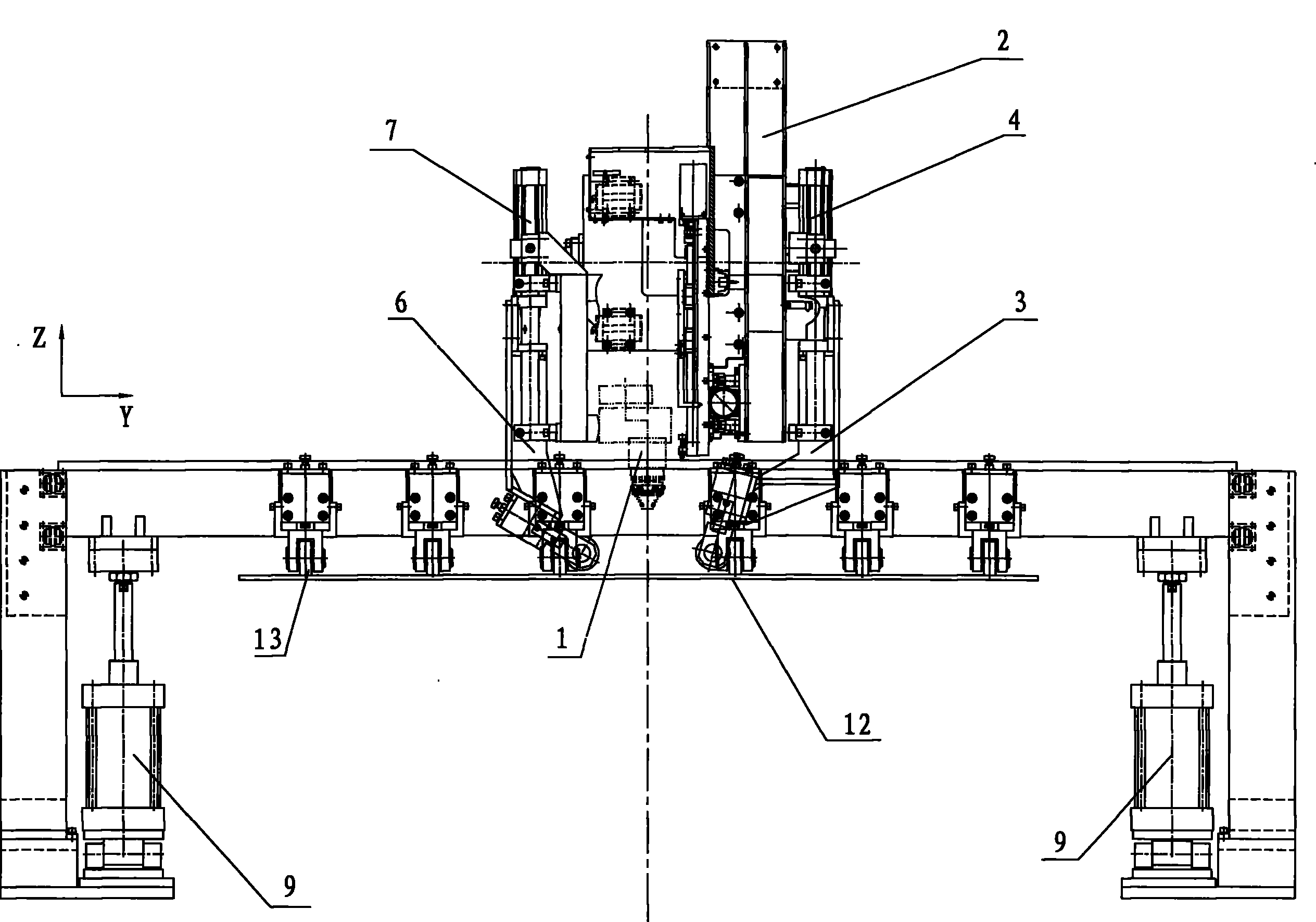
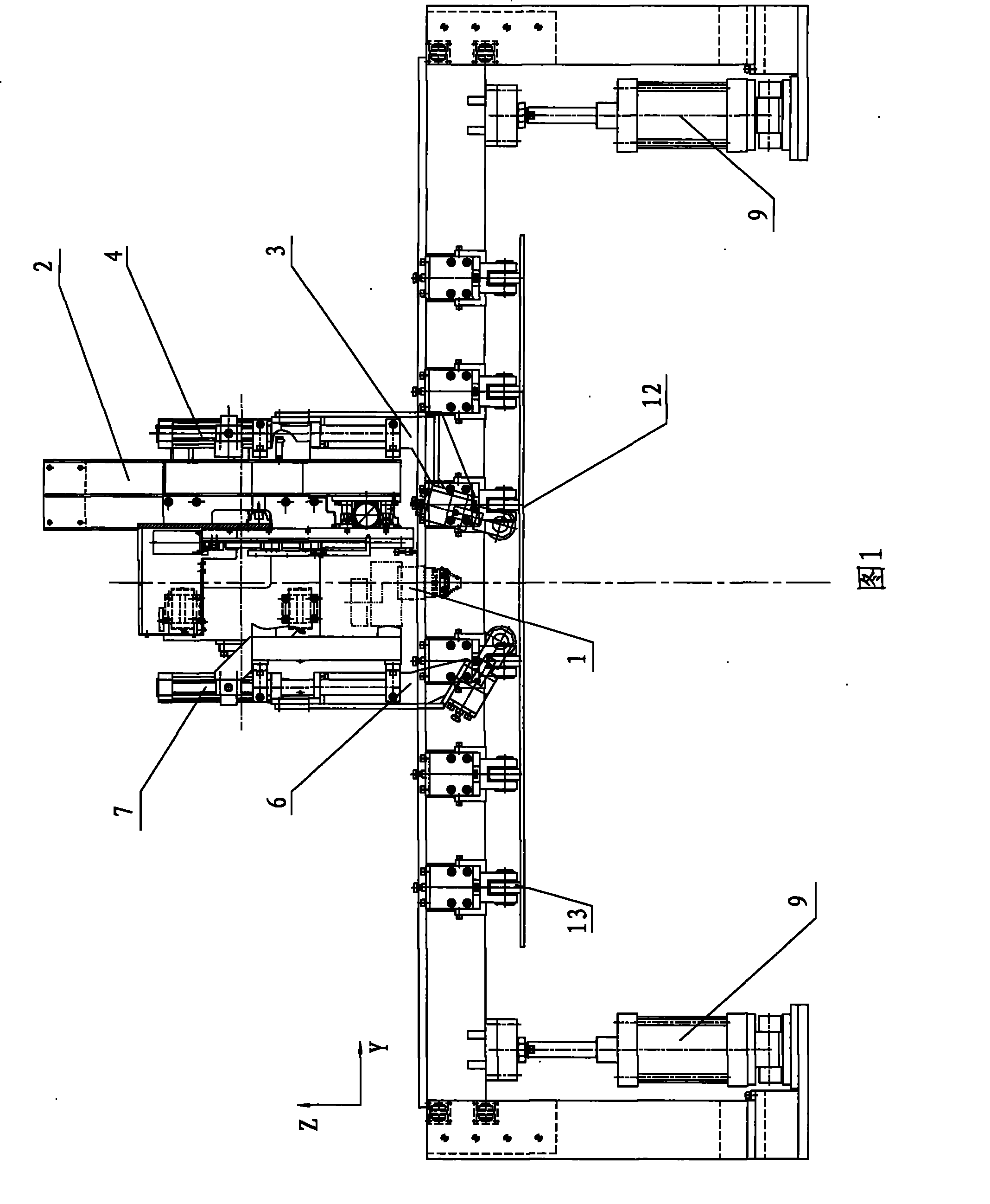
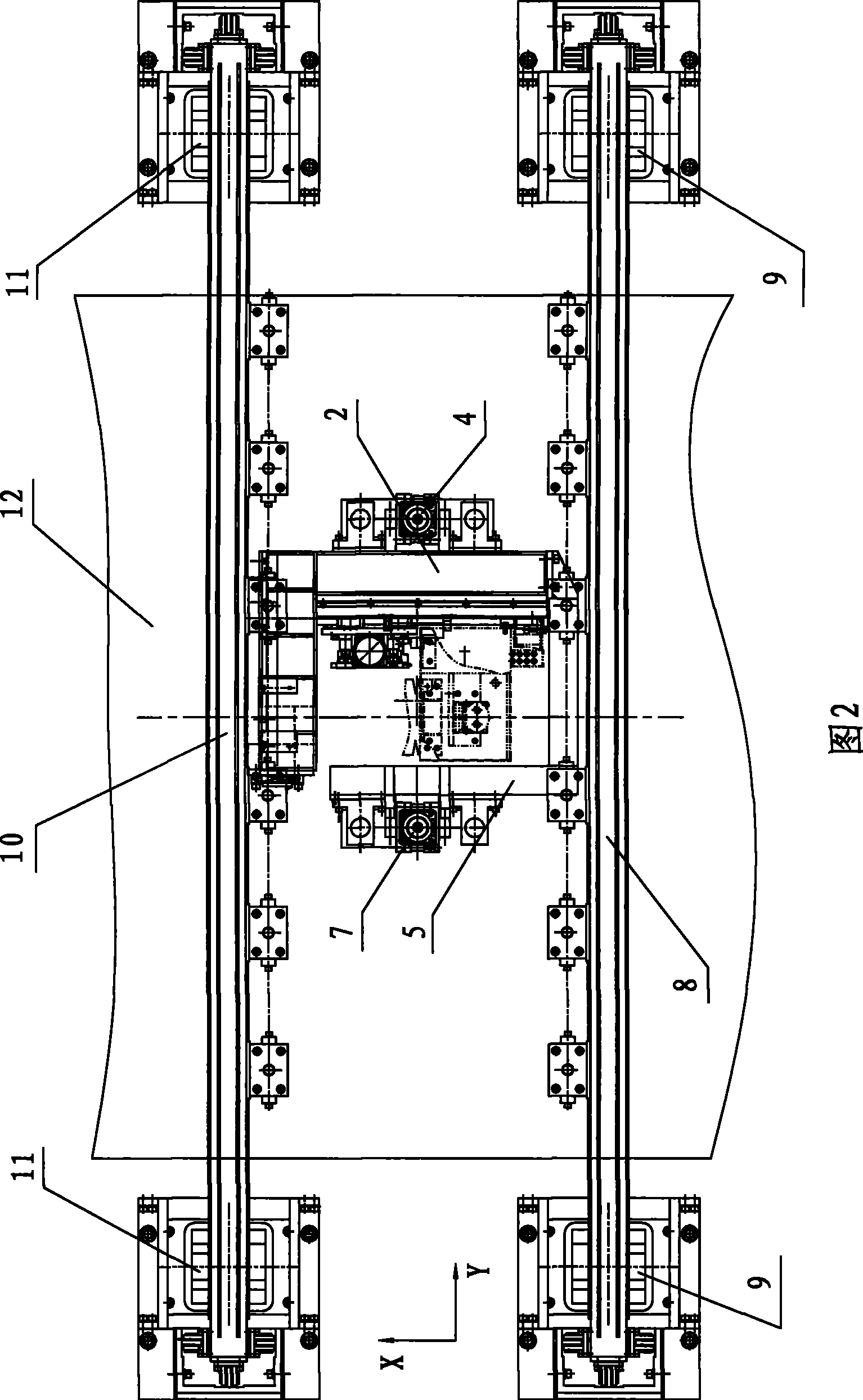
[0015] As shown in Fig. 1 and Fig. 2, the present invention is installed on the gantry frame, including laser head 1, Y-direction sliding table 2 and front and rear compression beams 8,10. The front and rear pressing beams 8 and 10 are arranged above the gantry workbench so as to move up and down, and are respectively located on the front and rear sides of the laser head 1 . The two ends of the front compression beam 8 are connected with the third drive cylinder 9 to control its up and down movement, and the two ends of the rear compression beam 10 are connected with the fourth drive cylinder 11 to control its up and down movement. A plurality of pressing wheels 13 are evenly distributed on the front and rear pressing beams 8 and 10 respectively. The Y-direction sliding table 2 installed on the beam of the gantry frame is located between the front and rear c...


PUM


Abstract

The invention relates to a mechanical pressing device, particularly a novel laser welding pressing device for pressing and leveling plate materials during the laser stitch welding process. The device is arranged on a gantry and comprises a laser head, a Y-directional slipway, and a front and a rear pressing beams, wherein the front and the rear pressing beams are arranged at the upper part of a gantry worktable in a vertical reciprocating manner; a plurality of pressing wheels are respectively arranged on the front and the rear pressing beams; the Y-directional slipway mounted on the gantry beam is positioned between the front and the rear pressing beams and can carry out a reciprocating movement along the Y direction; a right press roll which can move up and down is arranged on one side of the Y-directional slipway, and the laser head and a installation base are arranged on the other side, and a left press roll which can move up and down is arranged on the installation base; the laser head and the left and the right press rolls are coupled with the Y-directional slipway; the laser head is positioned between the left and the right press rolls, and the laser head can carry out a reciprocating movement along the X direction and the Z direction; and the laser head work area is surrounded by the left and the right press rolls and the front and the rear pressing wheels. The device has the advantages that the gap and the flatness between a thin plate and a thick plate can be guaranteed and the welding effect is good.

Description

technical field [0001] The invention relates to a mechanical pressing device, in particular to a novel laser welding pressing device for pressing and leveling plates in the process of laser stitch welding. Background technique [0002] During the development of a certain type of stainless steel plate laser welding equipment, it was found that during laser stack welding, due to the uneven thickness of the plate itself, and the unevenness of the plate itself, there will be a small gap when the two plates are stacked. When the gap exceeds 0.1mm and the flatness exceeds 0.1mm, it will directly affect the welding quality, which will cause potential safety hazards in the welded plates. Contents of the invention [0003] In order to solve the above-mentioned shortcomings of the small gap between the two plates during laser stitch welding, the purpose of the present invention is to provide a new type of laser welding that can eliminate the gap between the two thin and thick plates...

Claims


Application Information

Patent Timeline
Patent Type & Authority Patents(China)
IPC IPC(8): B23K26/42B23K37/053B23K26/08B23K26/20
CPCB23K37/0217B23K2203/04B23K26/246B23K2201/18B23K26/023B23K37/0408B23K26/0884B23K37/0435B23K26/037B23K26/244B23K2101/18B23K2103/05
Inventor 刘勇吴振军孙元魏强
Owner SHENYANG INST OF AUTOMATION - CHINESE ACAD OF SCI
Learn More