Welding clamp of total vehicle frame

A frame welding and fixture technology, applied in welding equipment, auxiliary welding equipment, welding/cutting auxiliary equipment, etc., can solve the problems of low processing efficiency, affecting the appearance of products, inaccurate welding position, etc. Relative displacement, the effect of improving accuracy

Inactive Publication Date: 2009-03-04
庄添财
View PDF0 Cites 44 Cited by
  • Summary
  • Abstract
  • Description
  • Claims
  • Application Information

AI Technical Summary

Problems solved by technology

In the current welding process, due to the lack of tools for clamping and positioning these components to be welded, relative movement between components often occurs during welding, so the operator needs to constantly adjust the position of each component,...

Method used


Image

  • Welding clamp of total vehicle frame
  • Welding clamp of total vehicle frame
  • Welding clamp of total vehicle frame

Examples


Embodiment Construction

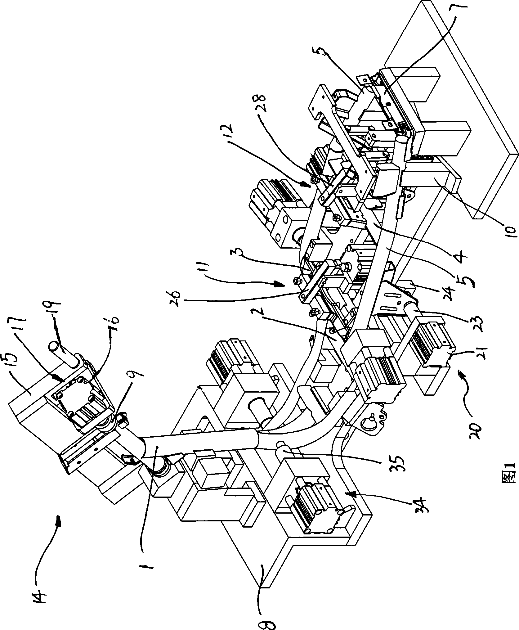
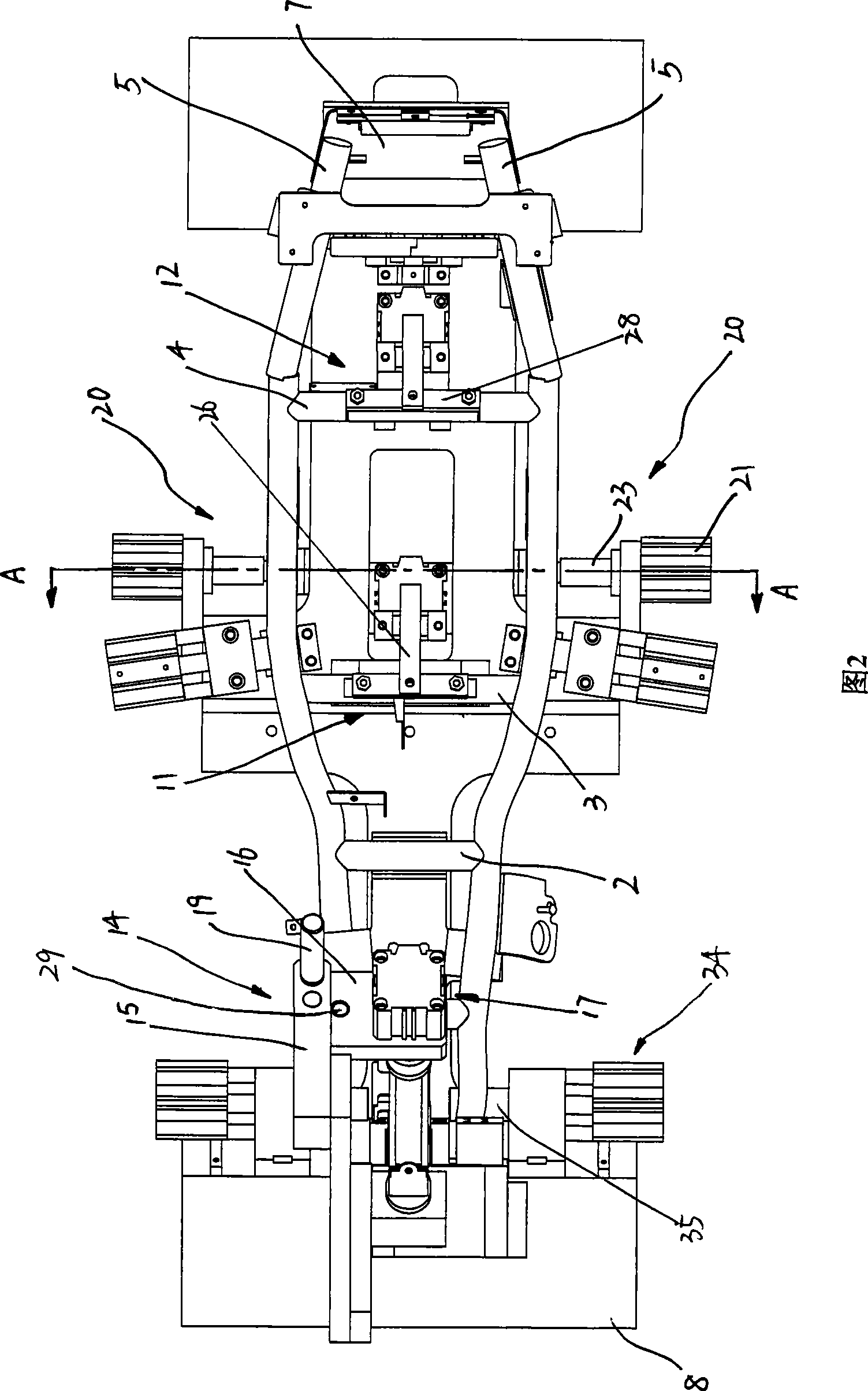
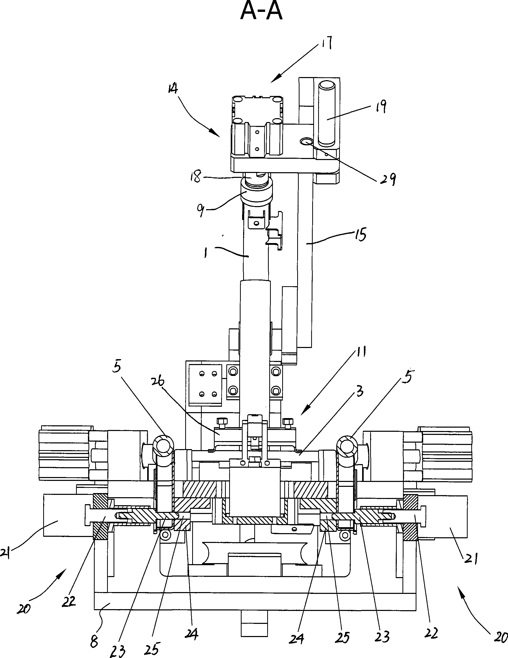
[0017] Referring to accompanying drawings 1 to 4, a general frame welding fixture includes a base frame 8, a plurality of brackets 10 fixedly arranged on the base frame 8 for supporting welded workpieces . A clamping device arranged on the base frame 8 and partly pressed against the workpiece to be welded. The plurality of brackets 10 respectively support the main beam frame 1 to be welded, the front connecting pipe 2, The helmet bucket fixing seat 3, the rear connecting pipe frame 4, the rear frame assembly 7 and a pair of bent pipe frames 5, and the plurality of brackets 10 are fixedly connected to the base frame according to the positional relationship between the components to be welded 8 on.

[0018] The clamping device includes a headstock fixing seat 14 positioned at the front of the base frame 8 for fixing the main girder frame 1 (the left side is "front" in the accompanying drawing 1, and the right side is "rear"). The front portion of frame 8 has support 15, and des...


PUM


Abstract

The invention relates to a welding fixture of a main chassis, which comprises a pedestal, a plurality of bearing blocks used for bearing welded workpieces and fixedly arranged on the pedestal, and a clamping device arranged on the pedestal with a part propped up against the workpieces to be welded. The clamping device comprises a headstock fixing seat positioned at the front part of the pedestal; a second workpiece table is fixedly arranged at the rear part of the pedestal; and a first workpiece table is also arranged between the headstock fixing seat and the second workpiece table. The welding fixture can rapidly position and fix each component to be welded, thereby improving the accuracy of welding positions, and further improving processing quality; in addition, the invention allows the multi-step welding during the one-time process of clamping, thereby improving processing efficiency.

Description

technical field [0001] The invention relates to a welding jig for a general frame, in particular to a tool for positioning and clamping parts when welding the general frame of a motorcycle. Background technique [0002] The total frame of the motorcycle usually includes a main beam frame welded together, a front connecting pipe, a helmet bucket fixing seat, a rear connecting pipe frame, a pair of bent pipe frames and a rear frame assembly, as shown in Figure 5. In the current welding process, due to the lack of tools for clamping and positioning these components to be welded, relative movement between components often occurs during welding, so the operator needs to constantly adjust the position of each component, resulting in low processing efficiency; at the same time , It is also easy to cause inaccurate welding positions, so that complex adjustments are required before assembly, so indentations are often left on the product, which affects the appearance of the product. ...

Claims


Application Information

Patent Timeline
IPC IPC(8): B23K37/053
Inventor 卢国荣薛晓马丁雷敏
Owner 庄添财
Why Eureka
Try Eureka