Electric loading test device and method for automobile steering system

A technology of loading test device and automobile steering system, which is applied in the direction of vehicle steering/bump performance, measuring device, vehicle testing, etc., and can solve the adverse effects of loading system performance, nonlinearity, poor dynamic response, and failure to meet the subjective and objective requirements of the steering system. Objective evaluation and other issues to achieve the effect of good test equipment

Inactive Publication Date: 2009-03-04
TRW AUTOMOTIVE COMPONENTS SHANGHAI
View PDF0 Cites 19 Cited by
  • Summary
  • Abstract
  • Description
  • Claims
  • Application Information

AI Technical Summary

Problems solved by technology

Spring loading simulates the ground resistance when the car turns by adjusting the preload of the spring. However, the ground resistance simulated by spring loading is linearly related to the displacement of the spring and does not change with the speed of the vehicle. During the test, it cannot reflect the tires and the ground in real time. contact relationship between
The steering system loading device that uses hydraulic or pneumatic loading can make up for the shortcomings of the above-mentioned passive loading device, but due to the strong nonlinearity and poor dynamic response of the hydraulic and pneumatic loading device itself, it will have an adverse effect on the performance of the loading system. It cannot meet the requirements of subjective and objective evaluation of the steering system under various driving conditions

Method used


Image

  • Electric loading test device and method for automobile steering system
  • Electric loading test device and method for automobile steering system
  • Electric loading test device and method for automobile steering system

Examples


Embodiment Construction

[0016] The present invention will be further described below in conjunction with the embodiments shown in the accompanying drawings.

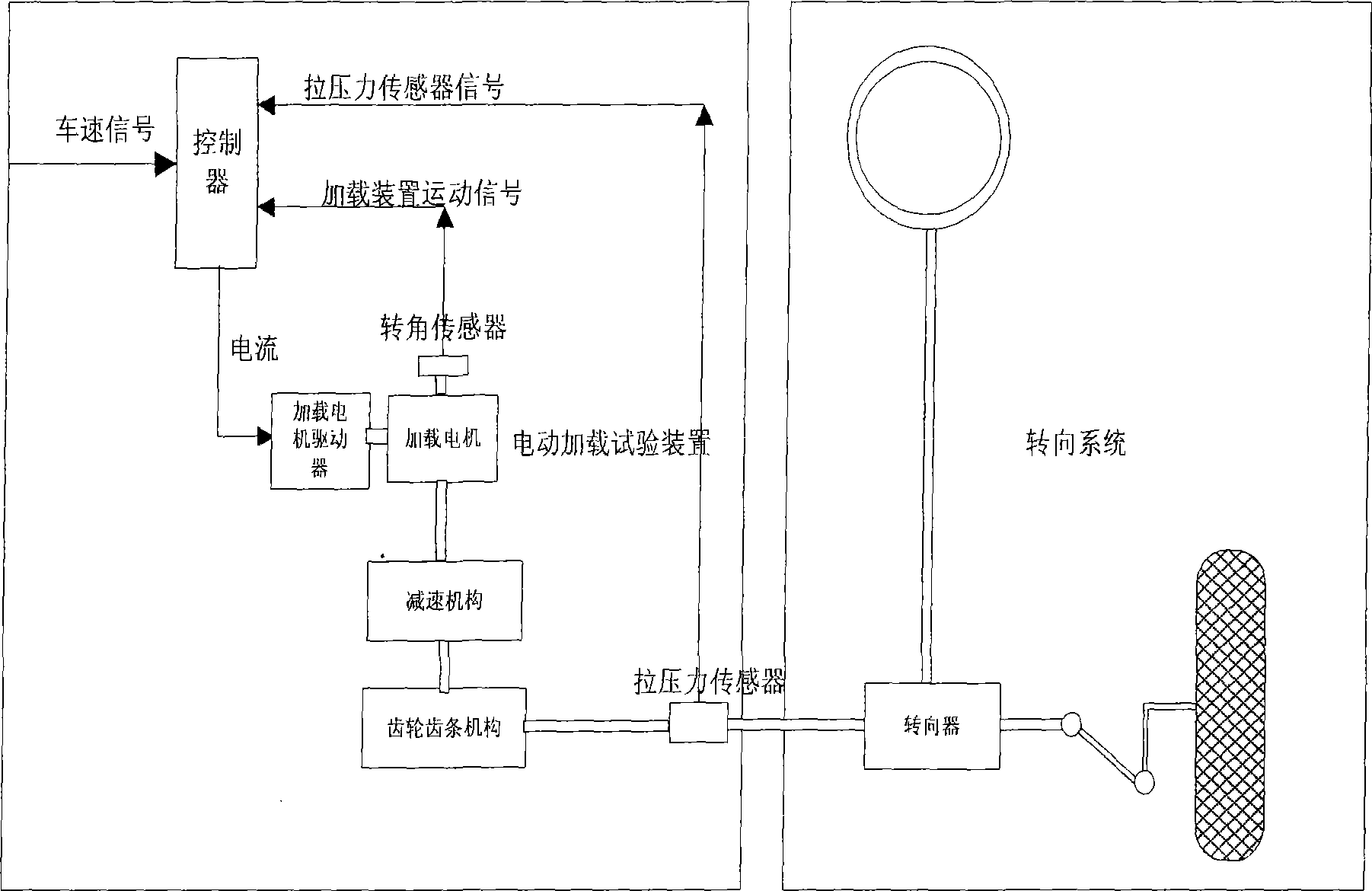
[0017] Depend on figure 1 As shown, an electric loading test device for an automobile steering system includes a loading motor driver, a loading motor (such as a permanent magnet synchronous motor or a DC motor), a reduction mechanism (such as a worm gear), and a motion conversion mechanism (such as a rack and pinion mechanism) , load force sensor (such as pull pressure sensor), load motion sensor (such as rotation angle sensor or displacement sensor) and controller. The motor is connected with the reduction mechanism to form a deceleration and torque increasing device. The reduction mechanism is connected with the gear in the rack and pinion mechanism to change the rotational motion of the motor into a linear motion. The rack in the rack and pinion mechanism is connected with the steering gear of the steering system. The rack is connected to ...


PUM


Abstract

The invention provides an electric load test device for automobile steering system. A driving speed signal and a steering wheel rotation angle which is detected by a rotation angle sensor or a displacement sensor are inputted in a controller. According to a vehicle model, the controller calculates and generates a dynamic steering system loading command force signal in real time. The loading command force signal, a practical loading force signal detected by a tension and pressure sensor, and the rotation angle or displacement signal detected by the rotation angle sensor or the displacement sensor are all together inputted in a feedforward compensation module and a PID force closed-loop control module (control scheme 1) or a two freedom degree internal mold force control module (control scheme 2) of the controller to calculate a loading force control signal which is used for loading rectilinear moving force on the gear rack of the steering device of the steering system. The electric load test device has quick system response speed, and can correctly simulate the returnable force of the steering system and high frequency (20Hz-40Hz) vibratory force caused by a plurality of interference factors such as the shimmy of the steering wheel and uneven road surface and so on under varieties of running conditions.

Description

technical field [0001] The invention belongs to the technical field of automobiles, and relates to a loading test device, in particular to an electric loading test device for an automobile steering system. Background technique [0002] Currently, the loading systems for testing the performance of automobile steering systems such as EPS systems mainly use passive loading methods, such as spring loading, etc., and active loading methods, such as hydraulic loading or pneumatic loading. Spring loading simulates the ground resistance when the car turns by adjusting the preload of the spring. However, the ground resistance simulated by spring loading is linearly related to the displacement of the spring and does not change with the speed of the vehicle. During the test, it cannot reflect the tires and the ground in real time. contact relationship between them. The steering system loading device that uses hydraulic or pneumatic loading can make up for the shortcomings of the above...

Claims


Application Information

Patent Timeline
Patent Type & Authority Applications(China)
IPC IPC(8): G01M17/06G01M17/007
Inventor 陈慧张臻卓桂荣
Owner TRW AUTOMOTIVE COMPONENTS SHANGHAI
Why Eureka
Try Eureka