Drive source of automatic door

A driving source, automatic door technology, applied in electric components, magnetic circuit rotating parts, manufacturing motor generators, etc., can solve the problem of switching labor and other problems, and achieve the effect of reducing the opening and closing load and reducing the opening and closing resistance.

Inactive Publication Date: 2009-03-04
SUMITOMO HEAVY IND LTD
View PDF1 Cites 2 Cited by
  • Summary
  • Abstract
  • Description
  • Claims
  • Application Information

AI Technical Summary

Problems solved by technology

[0007] Although automatic doors have been rapidly popularized in various places in recent years, the problem that exists in the installation of automatic doors is how to secure the installation space of the driving source.
This problem is particularly prominent when replacing an existing manual door with an automatic door. In this regard, the conventional drive source may not have a compact configuration.
[0008] In addition, recently, the problem that has been paid attention to is the smoothness of opening and closing when the power is turned off (when the automatic door is not in operation).
In recent years, the development of magnetic materials has also progressed, and motors that are smaller and more efficient than before have been developed. However, such high-efficiency motors are manually switched off for some reason when there is a power failure or when the operation switch of the automatic door is turned off. (compared with a normal door that does not have a driving source for an automatic door) there is a problem that it takes a lot of effort to open and close

Method used


Image

  • Drive source of automatic door
  • Drive source of automatic door
  • Drive source of automatic door

Examples


Embodiment Construction

[0026] Hereinafter, an example of embodiment according to the present invention will be described in detail with reference to the drawings.

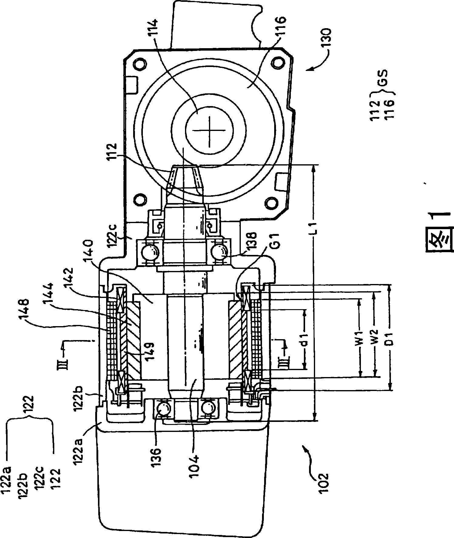
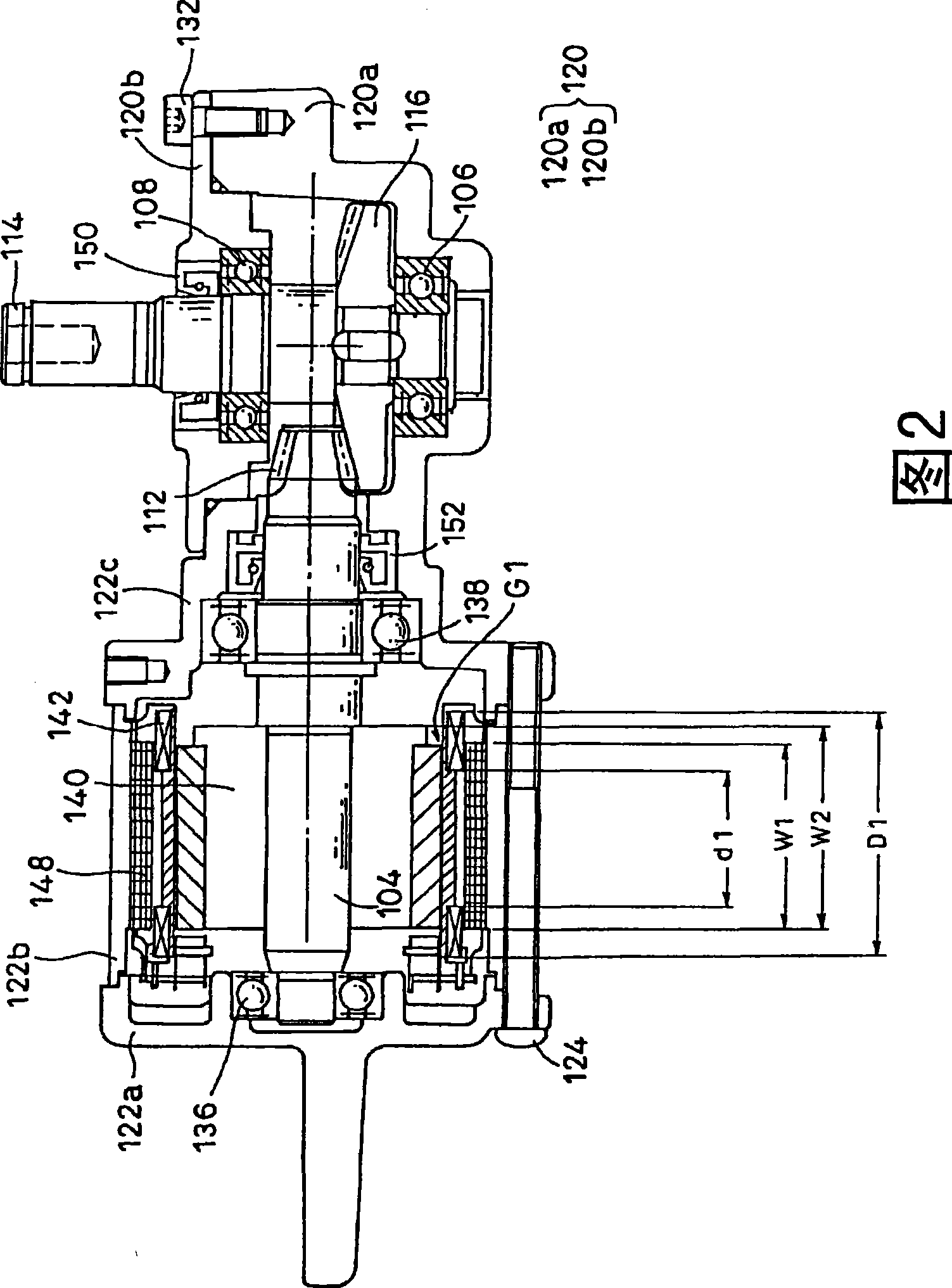
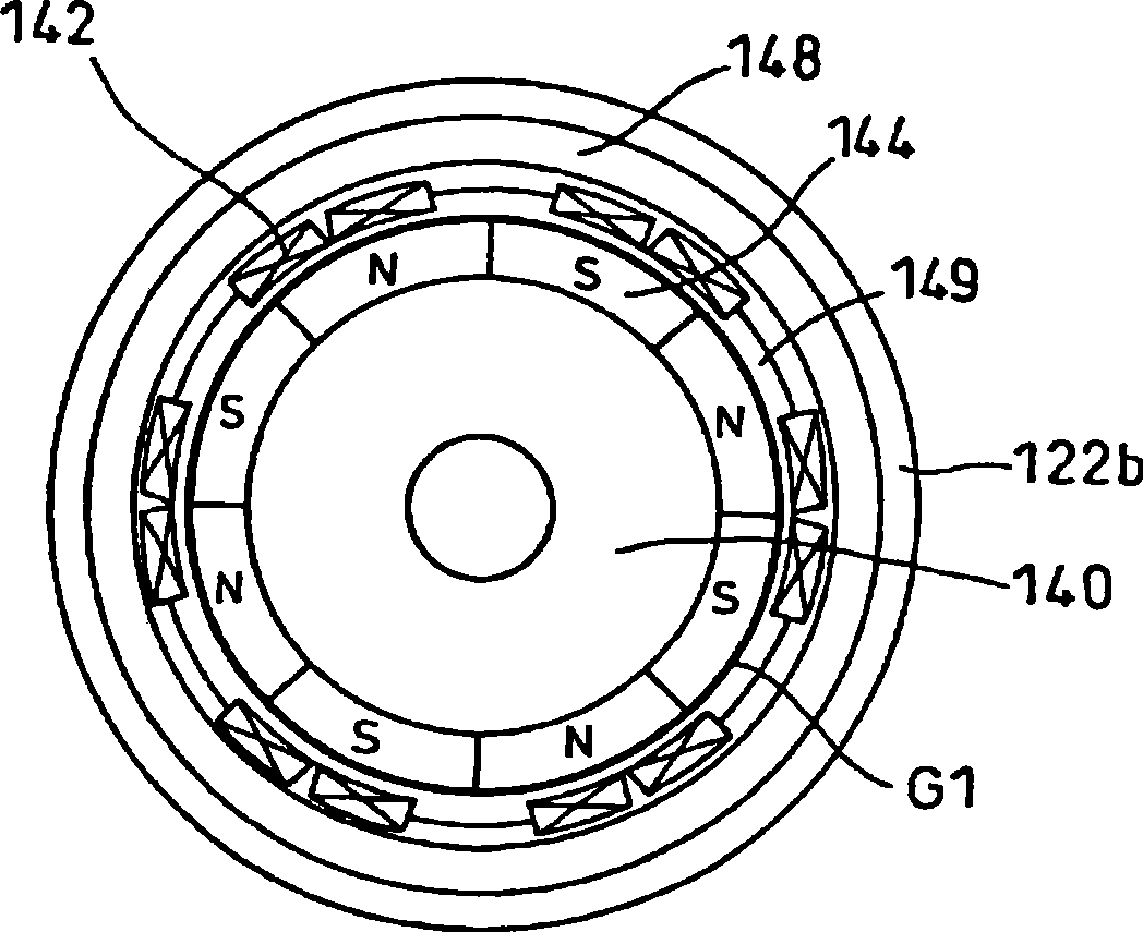
[0027] FIG. 1 is a front sectional view of a drive source 102 for an automatic door as an example of an embodiment of the present invention, and FIG. 2 is a side sectional view thereof, image 3 It is a sectional view along the arrow III-III line in Fig. 1, Figure 4 It is an overall configuration diagram of an automatic door using the driving source 102 .

[0028] The drive source 102 for this automatic door is used together with a speed reducer 130 . The output shaft 114 of the speed reducer 130 drives, for example, a pulley 302 to open and close an automatic door 303 via a door drive belt 301 (refer to Figure 4 ).

[0029] In this embodiment, the speed reducer 130 has a orthogonal gear set GS composed of a hypoid pinion 112 and a hypoid gear 116 .

[0030] In the drive source 102 , a drive source output shaft 104 for outputting r...


PUM


Abstract

The present invention can provide a drive source of an automatic door capable of suppressing the large-scale of the apparatus and alleviating the load of opening and closing door when the automatic door is at a non-action (when the power supply is closed). The drive source is together used with a reducer (130), and a drive source (102) of an automatic door is used to drive the automatic door. The drive source is provided with: a driver source output shaft (104), connected to the input shaft of the reducer (130) with transmission power (Figure is an example of integration); a rotor yoke (140), which may be integrally rotated with the driver source output shaft (104); a permanent magnet (144), fixed on the rotor yoke (140); a plurality of armature windings (142), provided on the external side of the radius direction of the permanent magnet (144) spaced with prescribed intervals, having no magnetic materials and bond into a flat shape; and a stator magnetic yoke (148 ), fixed on the armature winding (142).

Description

technical field [0001] The present invention relates to a driving source of an automatic door. Background technique [0002] In the past, publicly Figure 6 ~ Figure 8 The drive source 202 of the described automatic door (refer patent document 1). [0003] The driving source 202 of this automatic door is used together with the speed reducer 230 . [0004] The drive source 202 has a drive source output shaft 204 at its approximate center. The drive source output shaft 204 is supported by bearings at two points, and is rotatable relative to the housing 222 . On the drive source output shaft 204 , a permanent magnet 244 is provided and fixed via a rotor yoke 240 at a substantially central position in the axial direction. In addition, the stator yoke 248 is arranged so as to have a slight gap G2 from the surface of the permanent magnet 244 . The stator yoke 248 is fixed to the inner peripheral surface of the housing 222 . A plurality of armature windings 242 are in the form...

Claims


Application Information

Patent Timeline
IPC IPC(8): H02K1/27H02K1/12H02K3/04H02K21/14H02K7/116
CPCH02K1/146H02K3/52H02K15/03H02P3/06
Inventor 竹岛丰
Owner SUMITOMO HEAVY IND LTD
Why Eureka
Try Eureka