

Ultrasonic transducer, method of manufacturing ultrasonic transducer, ultrasonic diagnostic apparatus, and ultrasonic microscope
An ultrasonic and transducer technology, applied in the field of capacitive ultrasonic transducers, can solve problems such as the difficulty of using sound pressure and sensitivity to send and receive ultrasonic waves
- Summary
- Abstract
- Description
- Claims
- Application Information
AI Technical Summary
Problems solved by technology
Method used
Image

Examples
no. 1 Embodiment approach
[0048] Below, refer to figure 1 ˜ FIG. 8 describe the first embodiment of the present invention.
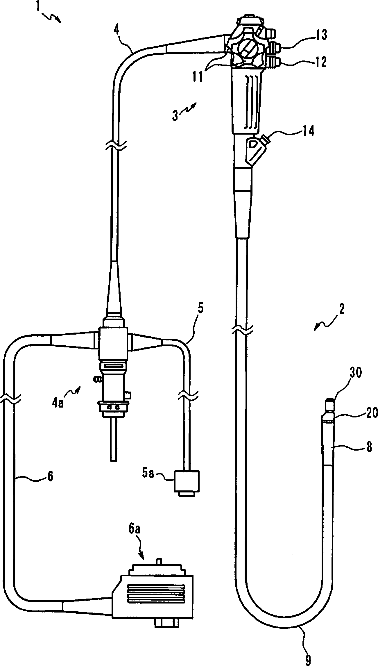
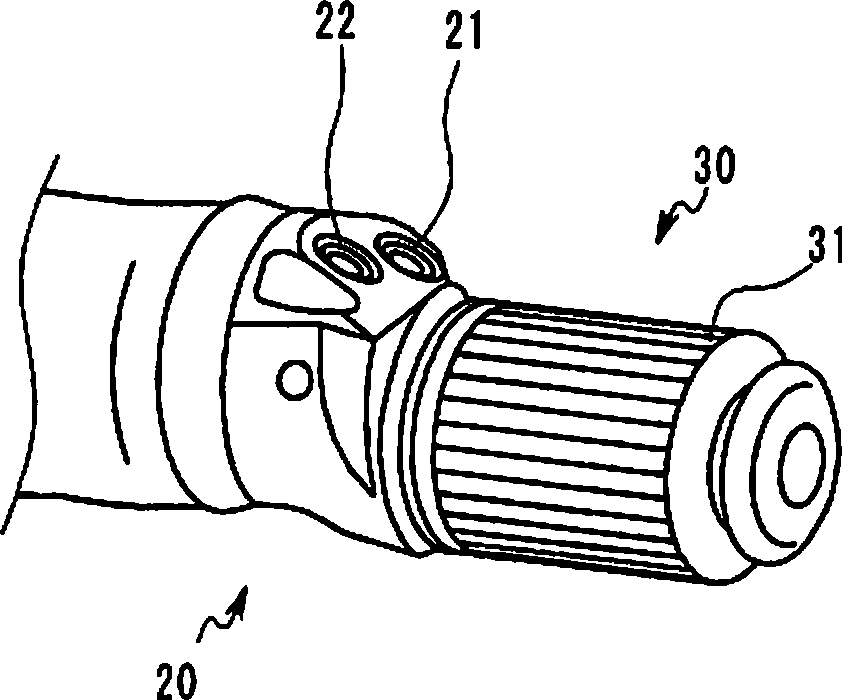
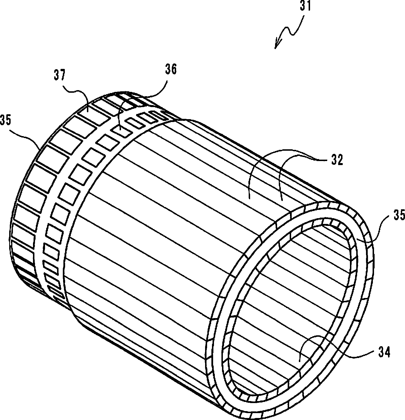
[0049] figure 1 It is an explanatory diagram showing a schematic configuration of an ultrasound endoscope. figure 2 It is a perspective view showing the structure of the distal end portion of the ultrasound endoscope. image 3 is a perspective view of the vibrator array.
[0050] In this embodiment, an example in which the present invention is applied to an ultrasonic endoscope as an ultrasonic diagnostic apparatus will be described. Such as figure 1 As shown, the ultrasonic endoscope 1 of this embodiment mainly consists of an elongated insertion part 2 introduced into the body cavity, an operation part 3 located at the base end of the insertion part 2, and a universal connection cable 4 extending from the side of the operation part 3. constitute.
[0051] An endoscope connector 4 a connected to a light source device (not shown) is provided at a base end portion of the uni...
no. 2 Embodiment approach
[0148] Hereinafter, a second embodiment of the present invention will be described with reference to FIG. 10 . 10 is a cross-sectional view of a vibrator component according to the second embodiment.
[0149]The second embodiment differs from the first embodiment only in the structure of the region where the electret is formed. Therefore, only this point of difference will be described below, and the same reference numerals will be assigned to the same components as those in the first embodiment, and description thereof will be appropriately omitted.
[0150] As shown in FIG. 10 , compared with the first embodiment, the vibrator member of this embodiment has a structure in which the region where the electret 130 is formed does not protrude in the direction of ultrasonic transmission than the region where the vibrator element 100 is formed.
[0151] In the vibrator member 33 a of the present embodiment, the surface irregularities on the ultrasonic-transmitting side are elimina...
no. 3 Embodiment approach
[0155] Below, refer to Figure 11 A third embodiment of the present invention will be described with reference to FIG. 12 . Figure 11 It is a plan view of the ultrasonic vibrator member 233 of this embodiment. Figure 12 is Figure 11 Sectional view of XII-XII.
[0156] The third embodiment differs from the configuration of the first embodiment only in the positional relationship between the region where the vibrator element is formed and the region where the electret is formed. Therefore, only this point of difference will be described below, and the same reference numerals will be assigned to the same components as those in the first embodiment, and description thereof will be appropriately omitted.
[0157] Such as Figure 11 As shown, the vibrator member 233 of this embodiment has a plurality of vibrator elements 200 arranged in a matrix when viewed from above (transmission direction of ultrasonic waves), and a plurality of vibrator elements 200 formed in regions separ...
PUM
| Property | Measurement | Unit |
|---|---|---|
| Thickness | aaaaa | aaaaa |
Abstract
Description
Claims
Application Information