Axial flow fan

An axial flow, fan technology, applied in non-variable displacement pumps, components of pumping devices for elastic fluids, machines/engines, etc. issues of balance

Active Publication Date: 2009-03-04
HANON SYST
View PDF3 Cites 15 Cited by
  • Summary
  • Abstract
  • Description
  • Claims
  • Application Information

AI Technical Summary

Problems solved by technology

[0012] However, in the conventional axial fan having the above wave structure, there is a problem that an imbalance occurs when the axial fan rotates, and if the clearance angle B is set too large, satisfactory reduction cannot be achieved. noise effect

Method used


Image

  • Axial flow fan
  • Axial flow fan
  • Axial flow fan

Examples


Embodiment Construction

[0044] Hereinafter, embodiments of the present invention will be described in detail with reference to the accompanying drawings.

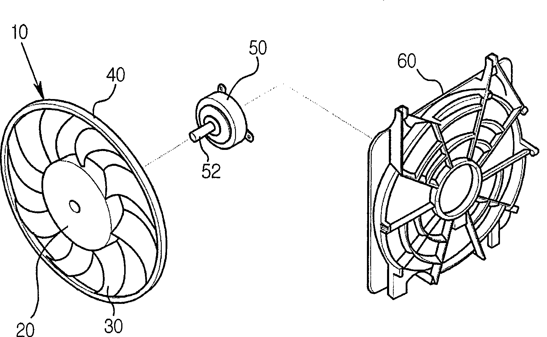
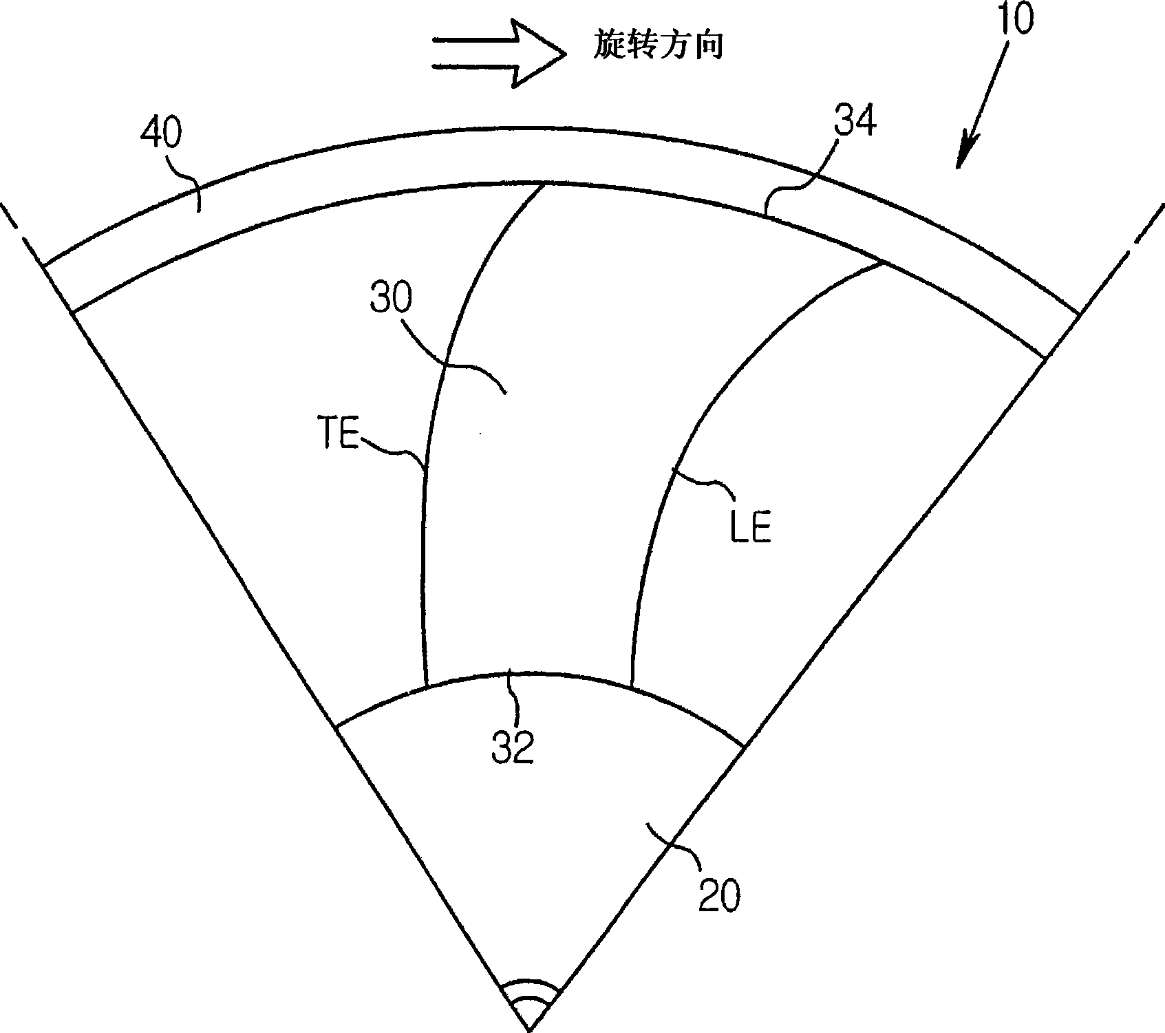
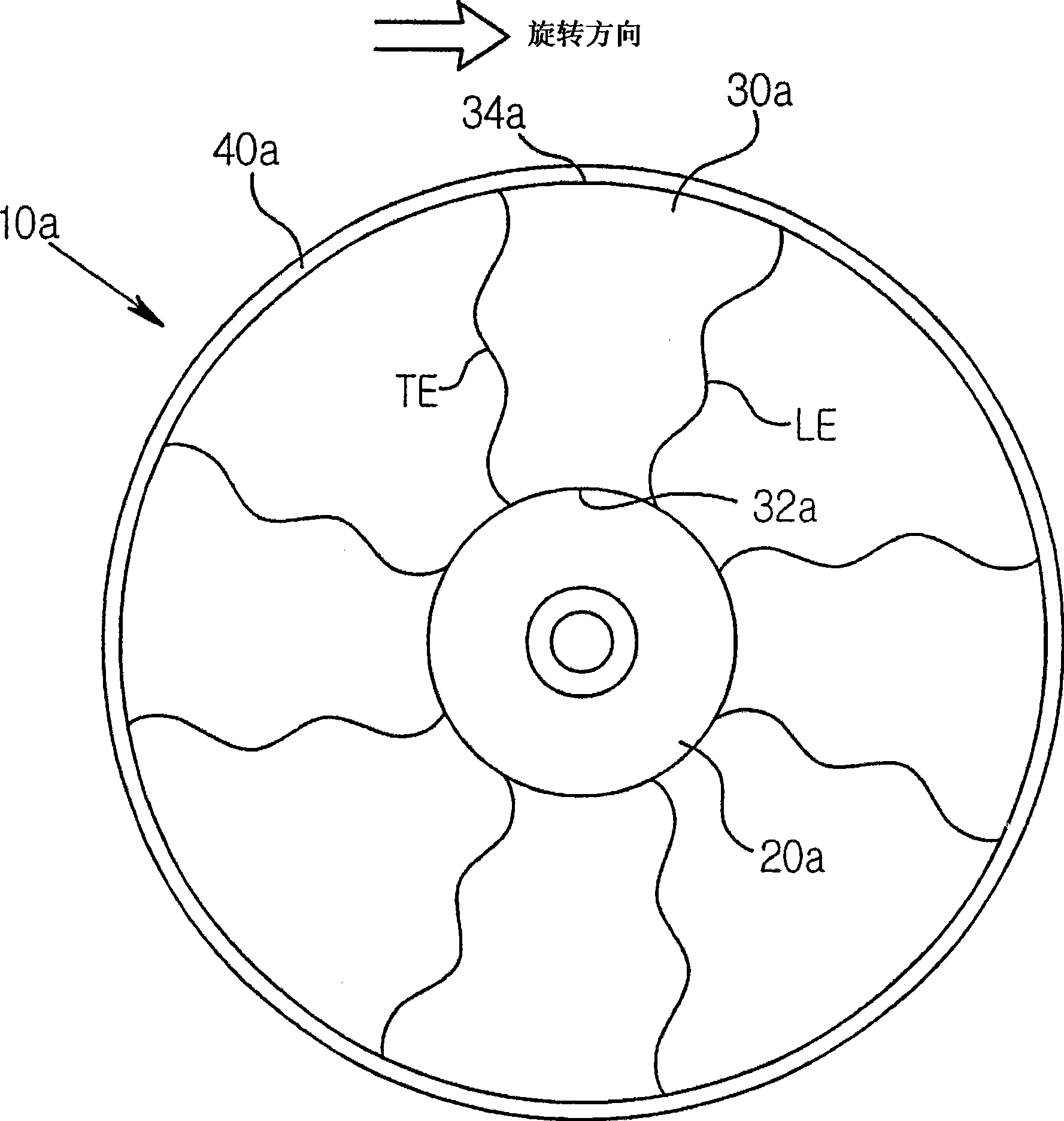
[0045] Figure 8 An axial fan according to the invention is shown. The axial fan 100 includes a hub 110; a plurality of blades 120 radially arranged around the hub 110 and having a sweep angle whose direction alternately changes in a region between a blade root 122 and a blade tip 124; and A fan strip 130 for integrally connecting the tip 124 of each blade 120 . In this embodiment, the illustrated axial fan 100 has nine blades 120 .

[0046]According to the present invention, when it is assumed that the angle between the two lines L1 and L2 passing through the center C of the hub 110 and the midpoints C1 and C2 of the root portions 122 of the two adjacent blades 120 in contact with the hub 110 is the blade When the distribution angle A1 of the blade is the clearance angle, the range of the distribution angle A1 of the blade along the rotation d...


PUM


Abstract

The present invention relates to an axial flow fan, and an object thereof is to make it capable of promoting structural stability so as to decrease deformation and unbalance of a blade as well as accomplishing low noise level by determining a distribution angle of the blade with an optimum clearance angle and thereby determining uneven rate of the blade.

Description

technical field [0001] The present invention relates to an axial flow fan, and more particularly, to an axial flow fan capable of improving structural stability to reduce deformation and unbalance of blades and achieve a low noise level. Background technique [0002] Such as figure 1 As shown, an axial fan 10 for cooling a heat exchange medium passing through the inside of a heat exchanger such as a vehicle radiator, condenser, etc. is provided with a hub 20 connected to a shaft 52 of a drive source 50 such as an electric motor, arranged radially A plurality of blades 30 at the outer circumference of the hub 20, and a fan band 40 for connecting blade tips to prevent deformation of the blades. The axial fan 10 is thus rotated by the rotational force transmitted from the driving source 50 to the hub 20 and blows air in the axial direction by the blades 30 . [0003] The cover 60 fixed to the heat exchanger serves to effectively guide the air blown by the axial fan 10 . The ...

Claims


Application Information

Patent Timeline
Patent Type & Authority Applications(China)
IPC IPC(8): F04D29/38
CPCF04D29/384F04D29/666F04D29/328F04D29/386F04D29/38F04D29/52
Inventor 赵景石朴世龙金禹准
Owner HANON SYST
Why Eureka
Try Eureka