
Vertical rail brace and rail wing fixation system composed of the vertical rail brace

A rail support and vertical technology, which is applied in the field of railway turnout wing rail fixing system manufacturing, can solve the problems that the stability of the wing rail cannot be guaranteed, and the fixing system needs to be improved.

Inactive Publication Date: 2009-03-11
CHINA RAILWAY BAOJI BRIDGE GRP
View PDF0 Cites 0 Cited by
  • Summary
  • Abstract
  • Description
  • Claims
  • Application Information

AI Technical Summary

Problems solved by technology

When the fasteners are loose, the stability of the wing rail cannot be guaranteed
Therefore, the fixing system of the wing rail needs to be improved

Method used


Image

  • Vertical rail brace and rail wing fixation system composed of the vertical rail brace
  • Vertical rail brace and rail wing fixation system composed of the vertical rail brace
  • Vertical rail brace and rail wing fixation system composed of the vertical rail brace

Examples


Embodiment 1

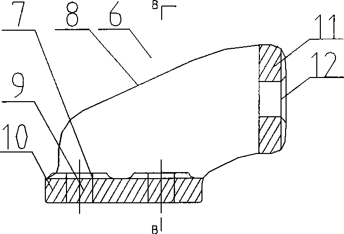
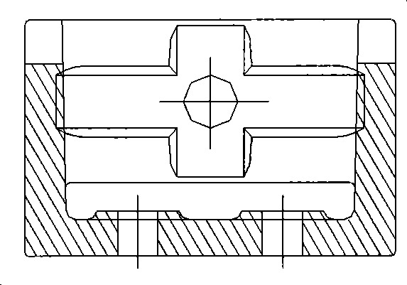
[0016] Embodiment 1: with reference to attached Figure 2~4 . The vertical rail brace 6 is composed of a vertical rail brace 11, an inclined rail brace side plate 12 and a rail brace bottom plate 10. The upper end of the inclined rail brace side plate 12 is connected with the vertical rail brace 11 to form an integral structure. The lower end of the support plate 11 is connected with the rail support base plate 10 to form an integral structure. There are connection holes on the surface of the vertical rail support plate 11 and it is connected with the wing rail 1 by locknuts and backing plates. hole. Vertical rail braces and buckle plates are realized by combining casting and machining. During assembly, the vertical rail braces are drilled with the Hack bolt holes of the backing plate, and then the backing plate and fasteners are installed to form frog wings. Rail fixing system structure, the existing technology can meet the processing requirements.

Embodiment 2

[0017] Embodiment 2: with reference to attached figure 1 and 6 ~7. On the basis of Embodiment 1, the frog wing rail fixing system composed of vertical rail braces includes wing rail 1, long core rail 2, short core rail 3, fork and tip rail 4, and vertical rail brace 6 passes through High-strength bolts and anti-loosening nuts are connected to the wing rail 1, the vertical rail brace 6 is connected to the bottom plate through four Huck bolts, the two ends of the backing plate are connected to the buckle plate 7 through fasteners, and the buckle plate 7 is connected to the switch tie bolts The sleeper is connected, and the wing rail forms a whole through the vertical rail support 6, lock nut, backing plate, fastener, buckle plate and switch sleeper.

Embodiment 3

[0018] Embodiment 3: On the basis of Embodiment 2, the frog wing rail fixing method is composed of vertical rail braces. The vertical rail braces are connected to the wing rails through high-strength bolts and locknuts. Bolt holes are drilled and connected to the bottom plate through four Huck bolts to achieve a never-loose connection. The two ends of the backing plate are connected to the buckle plate through fasteners. The rail support, lock nut, backing plate, fastener, buckle plate and switch sleeper form a whole, which realizes the reliable fixing of the wing rail.


PUM


Abstract

The invention relates to a vertical rail brace and a frog rail wing fixing system consisting of the vertical rail brace. The vertical rail brace consists of a vertical rail brace plate, an oblique rail brace lateral plate and a rail brace base plate; the upper end of the oblique rail brace lateral plate and the vertical rail brace plate are connected to form an integrated structure; and the lower end of the oblique rail brace lateral plate and the rail brace base plate are connected to form an integrated structure. The frog rail wing fixing system has the advantages that the frog rail wing fixing system has reliable fixing that the position of the rail wing is effectively fixed, assimilates the temperature force of lines between regions in the frog heel end part and ensures the geometric positions of the long point rail and the short point rail and the geometric position of the switch rail.

Description

technical field [0001] The invention relates to a vertical rail brace and a frog wing rail fixing system composed of the vertical rail brace, which belongs to the field of manufacturing railway turnout wing rail fixing systems. Background technique [0002] The temperature force of the section line is transmitted to the wing rails on both sides through the long and short core rails. The fixing system of the wing rails will directly affect the stability of the long and short core rails; It will directly affect the stability of the geometric shape of the point rail. The existing turnout is fixed by the fastener system on the inner and outer sides of the wing rail. Due to the limitation of the installation space, the inner fastener system can only be equipped with fasteners in some positions, and the rest of the parts are fixed by rigid buckling between the buckle plates. When the fastener is loose, the stability of the wing rail cannot be guaranteed. Therefore, the fixing sy...

Claims


Application Information

Patent Timeline
Patent Type & Authority Applications(China)
IPC IPC(8): E01B9/60E01B7/10
Inventor 王全生杨西费维周王阿利
Owner CHINA RAILWAY BAOJI BRIDGE GRP
Learn More