
Device for cleaning wall of dewatering cylinder for continuous centrifugal dewaterer

A centrifugal dehydrator and cleaning device technology, applied in the direction of drying solid materials, drying solid materials without heating, lighting and heating equipment, etc., can solve problems such as troublesome operation, loss of energy consumption, and impact on efficiency, and achieve the effect of convenient cleaning

Inactive Publication Date: 2009-03-11
陆书玉
View PDF0 Cites 3 Cited by
  • Summary
  • Abstract
  • Description
  • Claims
  • Application Information

AI Technical Summary

Problems solved by technology

[0002] At present, the gap-type centrifugal dehydrator is widely used in food, medicine, chemical industry, metallurgy and other industries in our country. When using it, the raw materials must be put into the filter cloth bag and fixed in the dehydrator, start the machine, and cut off the power supply after the moisture in the material is dehydrated. , the high-speed rotating cylinder is shut down, and the material can be taken out. This kind of dehydrator can keep the inside of the dehydrator clean for a long time, but this original processing method is labor-intensive, low productivity, and serious energy loss. The operation is unsafe, and the operation is troublesome, and the working hours are wasted
The continuous dehydrator can work continuously, which improves the labor productivity, but the wall of the dehydration cylinder tends to adhere to some small materials, which can seriously block the dehydration holes on the wall of the dehydration cylinder. The removal of these adhered materials needs to be done during shutdown In the case of opening the whole casing, in the highly automated assembly line production process, the use of this type of dehydrator to clean the adhesion on the wall of the dehydration cylinder becomes the main factor affecting the efficiency

Method used


Image

  • Device for cleaning wall of dewatering cylinder for continuous centrifugal dewaterer
  • Device for cleaning wall of dewatering cylinder for continuous centrifugal dewaterer
  • Device for cleaning wall of dewatering cylinder for continuous centrifugal dewaterer

Examples


Embodiment Construction

[0010] In order to further understand the invention content, characteristics and effects of the present invention, the following examples are given, and detailed descriptions are as follows in conjunction with the accompanying drawings:

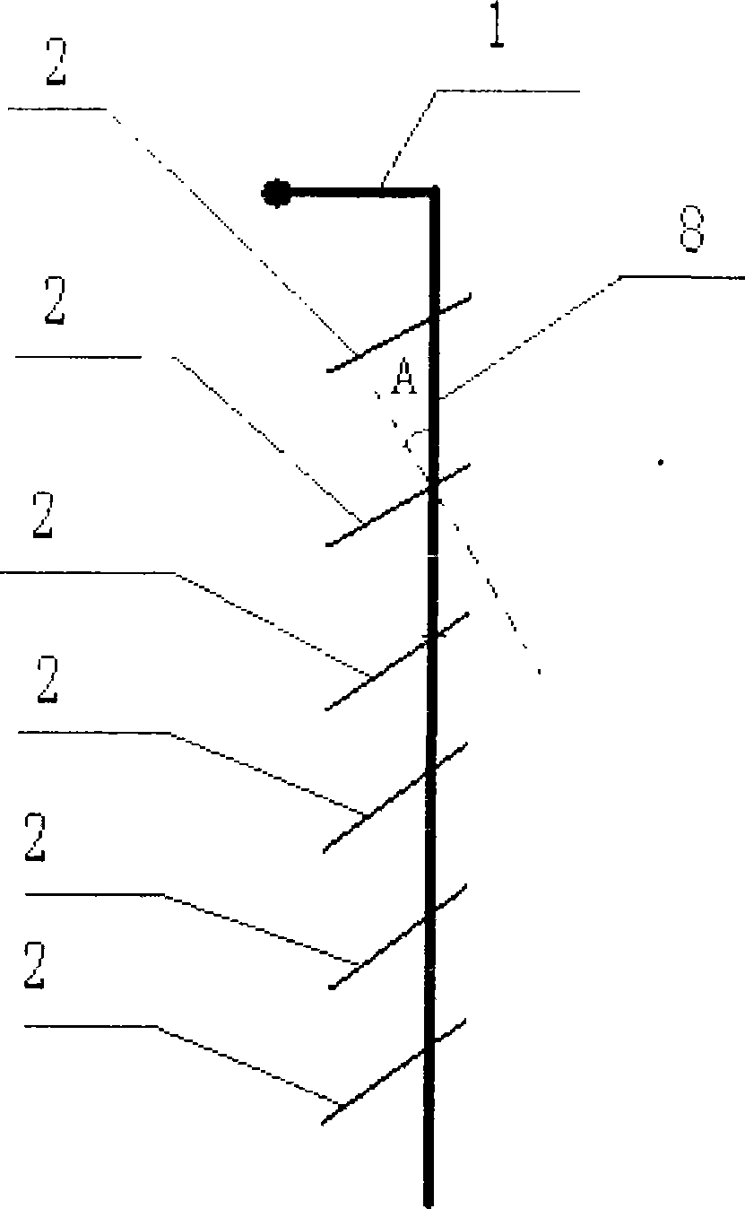
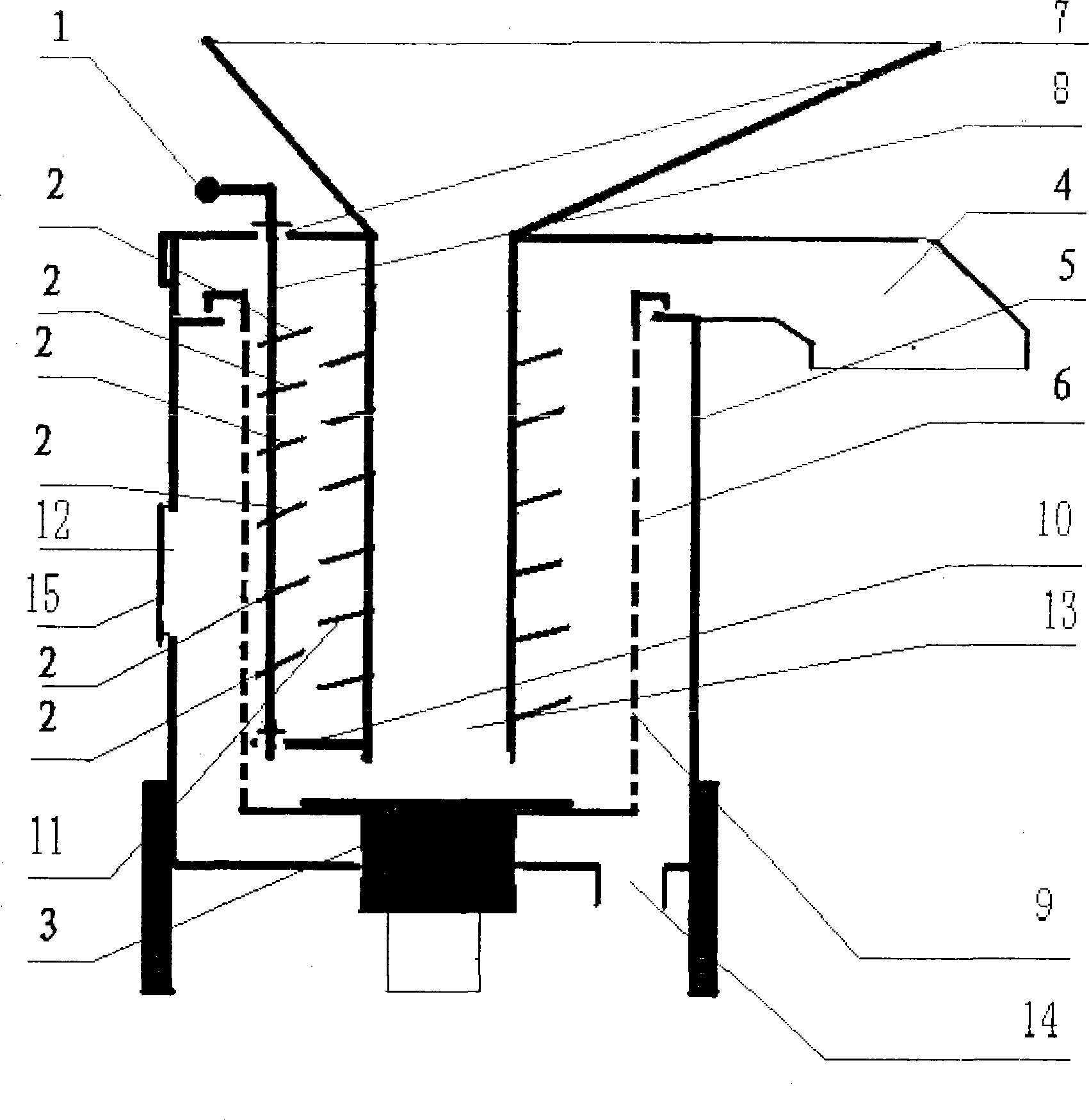
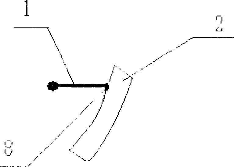
[0011] see Figure 1 and Fig. 2 shows that the present invention is mainly composed of connecting rod 8, blades 2 fixed on the connecting rod 8, and the like. The dehydration cylinder 6 rotates at high speed under the drive of the transmission wheel 3, and the materials adhering to the inner wall of the dehydration cylinder 6 are not in contact with the blades 2. The handle 1 is turned by hand to make the connecting rod 8 rotate at a certain angle, so that the blades 2 and the dehydration cylinder 6 The distance between the inner walls shrinks or the material adheres to the inner wall of the dehydration cylinder, and the force generated by the difference in speed between the inner wall of the rotating dehydration cylinder 6 and the blade 2 ca...


PUM


Abstract

The invention relates to a cleaning device of the wall of a dehydrating barrel of a continuous centrifugal dehydrator. The cleaning device is characterized by comprising a blade 2, a connecting rod 8 and the like; the blade 2 is driven to be close to the dehydrating barrel by the rotation of the connecting rod 8; when the centrifugal dehydrator is at work, the adhered working materials on the wall of the dehydrating barrel can be cleaned fast and conveniently, thus realizing the continuous work of the continuous centrifugal dehydrator. In addition, the invention is also characterized by easy manufacture, reliability and durability.

Description

technical field [0001] The invention belongs to the technical field of dehydration equipment, in particular to a device for cleaning the dehydration cylinder wall of a continuous centrifugal dehydrator. Background technique [0002] At present, the gap-type centrifugal dehydrator is widely used in food, medicine, chemical industry, metallurgy and other industries in our country. When using it, the raw materials must be put into the filter cloth bag and fixed in the dehydrator, start the machine, and cut off the power supply after the moisture in the material is dehydrated. , the high-speed rotating cylinder is shut down, and the material can be taken out. This kind of dehydrator can keep the inside of the dehydrator clean for a long time, but this original processing method is labor-intensive, low productivity, and serious energy loss. The operation is unsafe, and the operation is troublesome, and the working hours are wasted. The continuous dehydrator can work continuously...

Claims


Application Information

Patent Timeline
Patent Type & Authority Applications(China)
IPC IPC(8): F26B25/02F26B5/08
Inventor 陆书玉
Owner 陆书玉
Learn More