Optical film, mold for optical film and method for manufacturing optical film mold

A mold manufacturing and optical film technology, applied in optics, optical components, instruments, etc., can solve the problems of difficult design, general products and methods without suitable structures and methods, low optical film, etc., and achieve the effect of reducing deformation and damage.

Active Publication Date: 2009-03-11
ZHEJIANG JINHUI OPTOELECTRONIC MATERIAL CO LTD
View PDF0 Cites 5 Cited by
  • Summary
  • Abstract
  • Description
  • Claims
  • Application Information

AI Technical Summary

Problems solved by technology

[0004] In view of the fact that this type of damage is unavoidable, in order to avoid the above-mentioned pulling deformation, some operators have changed the prism 12 from a triangular design to a semi-cylindrical 13, hoping to use the wide top end of the semi-cylindrical 13 to have a strong ability to resist deformation, and at the same time The structure design of the arc top surface is used to slow down the deformation caused by the pulling of the protective film, but the luminance provided by the optical film with the semi-cylindrical 13 structure design decreases instead, which is usually significantly higher than that of the prism 12. The optical film is low, it is hard to call it a good design
[0005] This shows, above-mentioned existing optical film obviously still has inconvenience and defect in product structure and use, and urgently needs to be further improved
In order to solve the above-mentioned problems, the relevant manufacturers have tried their best to find a solution, but no suitable design has been developed for a long time, and there is no suitable structure and method for general products and methods to solve the above-mentioned problems. This is obviously a problem that relevant industry players are eager to solve

Method used


Image

  • Optical film, mold for optical film and method for manufacturing optical film mold
  • Optical film, mold for optical film and method for manufacturing optical film mold
  • Optical film, mold for optical film and method for manufacturing optical film mold

Examples


Embodiment Construction

[0037] In order to further explain the technical means and effects that the present invention adopts to achieve the intended purpose of the invention, below in conjunction with the accompanying drawings and preferred embodiments, the optical film, the mold for forming the optical film and the manufacturing method of the mold proposed according to the present invention are specifically described. Embodiments, structures, methods, steps, features and effects thereof are described in detail below.

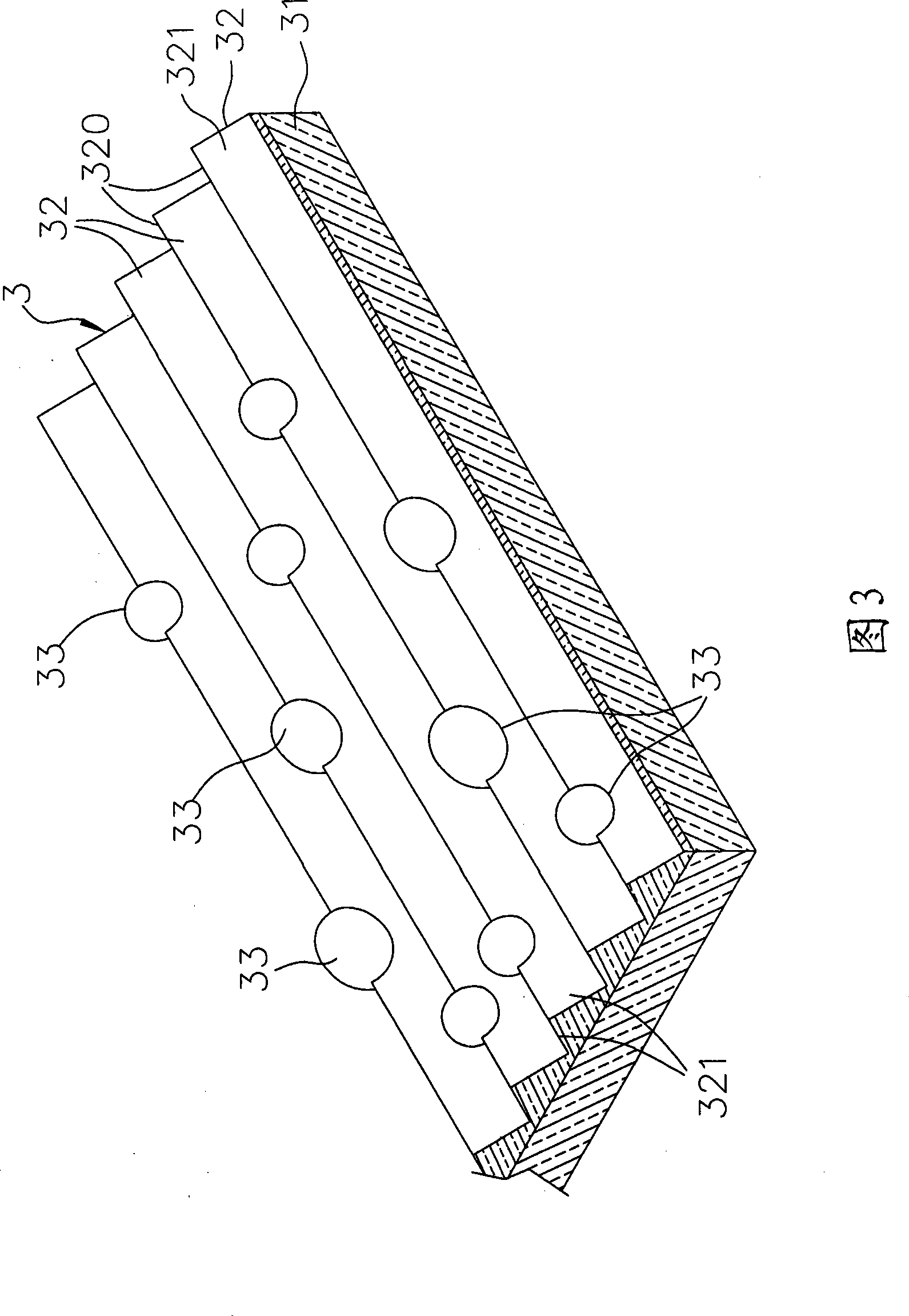
[0038] Please refer to FIG. 3 to FIG. 5 , which are respectively a three-dimensional schematic view, a right side view sectional view and a front side partial enlarged sectional view of an embodiment of the optical film of the present invention. An embodiment of the optical film of the present invention is in the shape of a transparent sheet to allow light to penetrate. The optical film 3 includes a sheet substrate 31, a plurality of prisms 32 extending back and forth and connected to ...


PUM


Abstract

The invention relates to an optical film, a die used for forming the optical film and a manufacturing method of the die. The optical film comprises a substrate, a plurality of prisms intermittently and convexly arranged on the top surface of the substrate and a plurality of spherical lenses respectively and convexly arranged on the peak of the prisms. Each prism is provided with two opposite inclined planes which extend upward obliquely to form a vertex angle. The spherical lenses provided with circular arc external surface extend externally consubstantially from the two inclined planes of the prism and is higher than the vertex angle of the prism. By the structure design of forming the spherical lens higher than the vertex angle of the prism on the prism peak, not only the distortion resistance and the scratch resistance of the prism vertex angle can be greatly improved, but also irregular refraction is generated by the optical line penetrating the optical film upward so as to improve the situation of a strip bright part and a strip dark part of the common optical film arrayed at interval, thus improving the imaging quality of monitors.

Description

technical field [0001] The invention relates to a light-transmitting film and a mould, in particular to an optical film whose surface is convexly provided with prisms, a mold for forming the optical film, and a manufacturing method of the mold. Background technique [0002] At present, liquid crystal displays have been gradually accepted by the public and have replaced traditional displays. The interior of liquid crystal displays is roughly divided into three blocks, one is the light source structure that provides light, the other is the liquid crystal structure that mainly produces images, and the other is Several sheets of thin optical films are arranged between the aforementioned two structures. These optical films can be divided into two types with diffusion function and light concentrating function. As far as the optical film 1 with light concentrating function is concerned, please refer to Figure 1 , FIG. 2, FIG. 1 is a side cross-sectional view of an existing optical ...

Claims


Application Information

Patent Timeline
IPC IPC(8): G02B5/00B29C33/38B29C33/42
Inventor 伍清钦
Owner ZHEJIANG JINHUI OPTOELECTRONIC MATERIAL CO LTD
Why Eureka
Try Eureka