

Maintenance machinery electrical system status monitoring with diagnose apparatus and monitoring and diagnose method
A technology for road maintenance machinery and electrical systems, applied in the field of electrical systems
Active Publication Date: 2010-12-01
ZHUZHOU CSR TIMES ELECTRIC CO LTD +1
View PDF0 Cites 0 Cited by
- Summary
- Abstract
- Description
- Claims
- Application Information
AI Technical Summary
Problems solved by technology
The purpose of this utility model is to solve these current problems. The main advantages are that the wiring of the original electrical control system is not changed, the hardware cost is not increased, the work intensity of technicians is reduced, and the accuracy and efficiency of diagnosis are improved.
Method used
View moreImage
Smart ImageViewing Examples

Examples
Embodiment Construction
Login to View More PUM
 Abstract
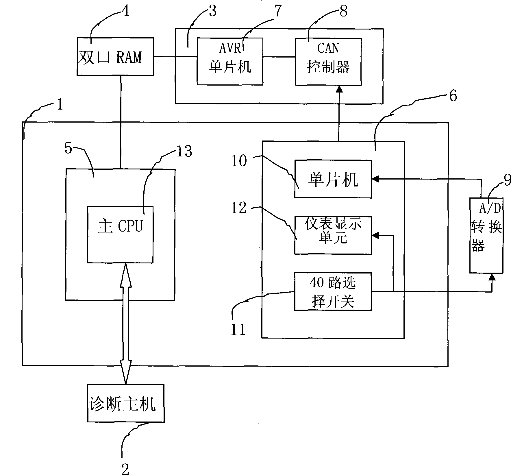
The invention relates to a status monitoring and diagnosing device of an electrical system of maintenance machinery, which comprises an electrical control system for the operation of the maintenance machinery, a diagnosing host, a CAN bus interface composed of an AVR singlechip and a CAN controller, an RAM with double ports and an A / D converter; a main CPU of a program control motherboard is connected with the AVR singlechip of the CAN bus interface by the RAM with double ports which realizes data exchange; the A / D converter is connected between a digital signal input end of a singlechip of a40-way display board and an analog signal output end of a 40-way selection switch of the 40-way display board; the main CPU of the electrical control system for the operation of the maintenance machinery is connected with a diagnosing host carrying data collection, analysis and diagnosing programs by an RS232 interface. By communicating with a program control host of the maintenance machinery andthe 40-way display board, the diagnosing host obtains program control signals and analog control signals, analyzes and finds out abnormality and realizes the purpose of diagnosing the electrical system of the maintenance machinery.
Description
Condition monitoring and diagnosis device and method for monitoring and diagnosing electrical system of road maintenance machinery technical field The utility model relates to an electrical system of a rail transit maintenance machine, in particular to a state monitoring and diagnosis device and a monitoring and diagnosis method for the electrical system of a road maintenance machine. Background technique At present, the electrical control system of domestic tamping vehicles adopts a set of program logic control system to carry out system control, coordination, logic operation, etc., but it lacks a fault diagnosis device that can operate during system failure, maintenance and debugging. Due to the large number of input and output signals and the complex logical relationship between the signals, fault detection has become a major problem for mechanized construction units. This device is designed for the current domestic D08-32 tamping vehicle. It is a set of large-scale roa...
Claims
Login to View More Application Information
Patent Timeline
 Patent Type & AuthorityPatents(China)
IPC IPC(8): G05B23/02
Inventor卢云波马世宏龚军王伟辉李懿
OwnerZHUZHOU CSR TIMES ELECTRIC CO LTD