Gun rivet

A technology of rivets and rivets, applied in the direction of rivets, screws, threaded fasteners, etc.

Inactive Publication Date: 2009-03-11
WURTH INT AG
View PDF1 Cites 9 Cited by
  • Summary
  • Abstract
  • Description
  • Claims
  • Application Information

AI Technical Summary

Problems solved by technology

This hammering does not allow the precise resolution of the force first into a pure feed force and only afterwards into an expansion force (US 3691924)

Method used


Image

  • Gun rivet
  • Gun rivet
  • Gun rivet

Examples


Embodiment Construction

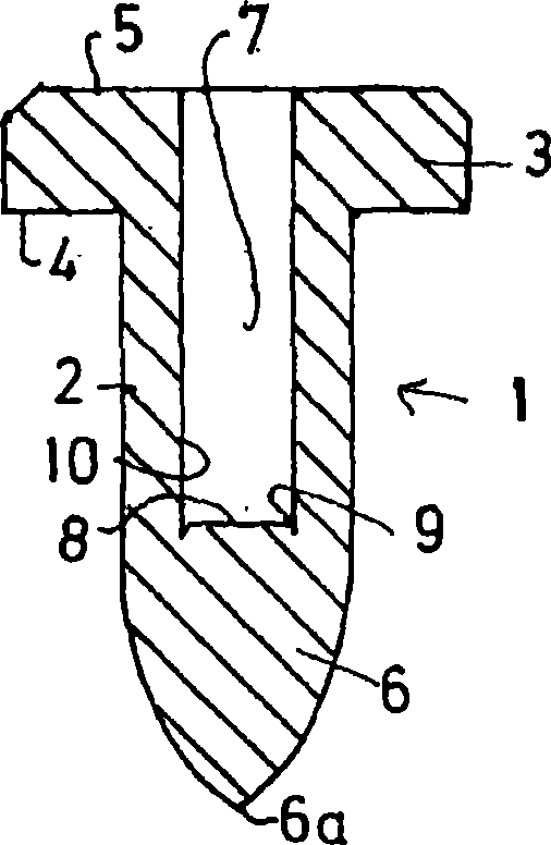
[0039] figure 1 A longitudinal section through a shooting rivet according to the invention is shown. The shooting rivet comprises a rivet body 1 which is designed in its central region as a rivet sleeve 2 . At one of the ends, a flange 3 is formed on the rivet body 1 , which flange 3 has a flat limiting surface on its underside 4 . The underside is the side facing in the direction of the rivet tip 6 . An active surface for accommodating a tool is provided on an upper side 5 , which is also designed to be flat or approximately flat, opposite the flat bottom side 4 .

[0040]At the end facing away from the flange 3, the rivet point 6 is formed, in which the cross-section of the rivet body decreases continuously up to a real point 6a. A recess 7 is formed in the rivet body 1 in the shape of a borehole, ie with a cylindrical cross-sectional shape. The recess 7 ends in a bottom 8 which is separated from the wall 10 of the recess 7 by a circumferential cutout 9 .

[0041] The s...


PUM


Abstract

The invention relates to a gun rivet and a device for installing the gun rivet. The gun rivet has a rivet body (1) with a flange at one end and a tip at another end. A cavity of borehole shape is disposed at sleeve section in the rivet body. The gun rivet as other gun rivets is shot into two sheets to be joined through sudden movement and rivet tip inserts in the sheets until the flange butts the upper side of the sheet, the pulling bolt is inserted into the cavity and connected with bottom of the cavity. The invention can be accomplished by resistance welding; pulling bolt is continuously pulled until oppositely positioned surface of the two sheet forms rivet head, then the pulling bolt is released from set gun rivet through such as shearing. The pulling bolt can be used in another mounting process.

Description

technical field [0001] The invention relates to a blind rivet designed as a shooting rivet, a device and a method for setting the blind rivet. Background technique [0002] Blind rivets have been known for a long time. The blind rivet is used to connect two elements to one another by means of a riveting process, wherein no access to the rear side is required. For this reason, blind rivets are especially suitable for use in situations where access to the rear of two elements to be connected to each other is not possible. In conventional blind rivets it is necessary to provide the elements to be joined with holes through which the rivet body is passed. The rivet mandrel is then pulled from the front side, which deforms the rivet on the back side to form the rivet head. [0003] It is also known to form the tip of the mandrel protruding from the front side of the rivet as a self-drilling tip, so that the drilling process can be carried out with corresponding tools during the...

Claims


Application Information

Patent Timeline
Patent Type & Authority Applications(China)
IPC IPC(8): F16B19/08B21J15/02
CPCB21J15/185B21J15/025F16B19/14F16B5/04F16B37/065F16B19/086B21J15/048F16B19/1045B21J15/043
Inventor U·弗兰克M·斯特罗贝尔
Owner WURTH INT AG
Why Eureka
Try Eureka