Eureka AIR delivers breakthrough ideas for toughest innovation challenges, trusted by R&D personnel around the world.

Clamp for laser welding of T-shaped connector

A technology of laser welding and fixtures, applied in laser welding equipment, welding equipment, manufacturing tools, etc., can solve problems such as deformation of T-shaped joints, achieve the effects of preventing welding deformation, simple structure, and convenient use

Inactive Publication Date: 2018-01-19
SOUTHWEST JIAOTONG UNIV
View PDF4 Cites 2 Cited by
  • Summary
  • Abstract
  • Description
  • Claims
  • Application Information

AI Technical Summary

Problems solved by technology

[0003] The main purpose of the present invention is to provide a fixture for laser welding T-joints, to solve the problem of deformation of T-joints in the prior art during welding

Method used


Image

  • Clamp for laser welding of T-shaped connector
  • Clamp for laser welding of T-shaped connector
  • Clamp for laser welding of T-shaped connector

Examples


Embodiment Construction

[0035] The present invention will be clearly and completely described below in conjunction with the accompanying drawings. Those skilled in the art will be able to implement the present invention based on these descriptions. Before the present invention is described in conjunction with the accompanying drawings, it should be pointed out that:

[0036] The technical solutions and technical features provided in each part of the present invention, including the following description, can be combined with each other under the condition of no conflict.

[0037] In addition, the embodiments of the present invention referred to in the following description are generally only a part of the embodiments of the present invention, rather than all the embodiments. Therefore, based on the embodiments of the present invention, all other embodiments obtained by persons of ordinary skill in the art without creative efforts shall fall within the protection scope of the present invention.

[0...


PUM


Abstract

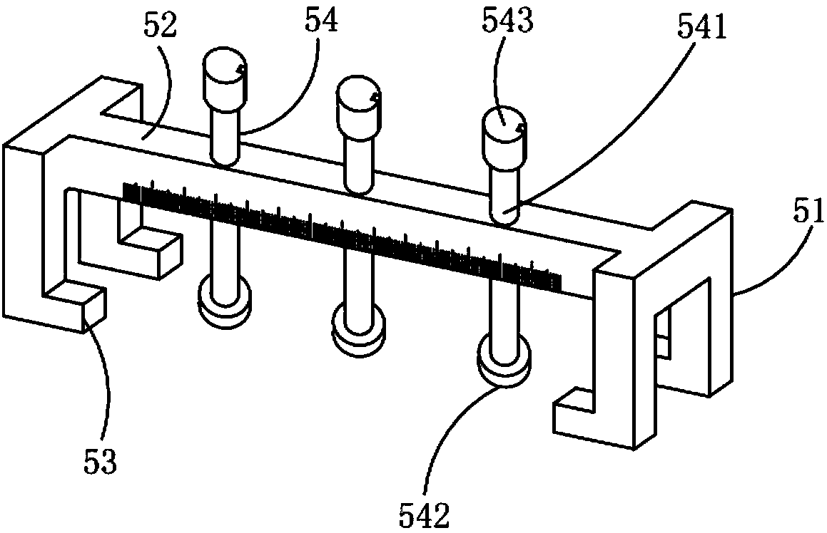
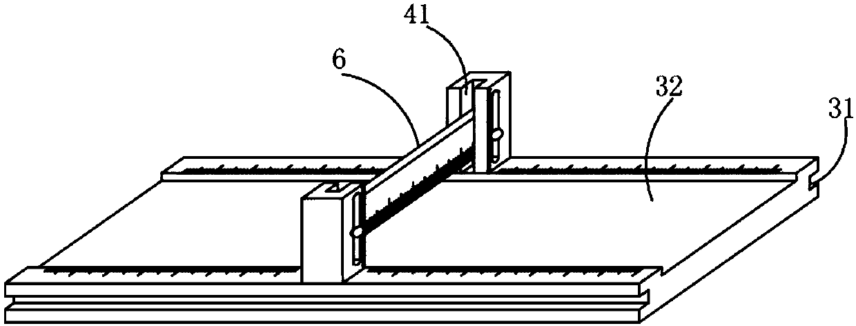
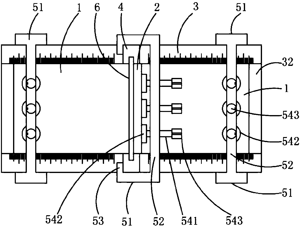
The invention discloses a clamp for laser welding of a T-shaped connector. The T-shaped connector comprises a base plate and a rib plate perpendicular to the base plate. The clamp comprises a locatingmechanism enabling the base plate and the rib plate to be perpendicular to each other in the welding process. The locating mechanism comprises a base, two stand columns which are perpendicular to thebase plate and located on the two sides in the axial direction of the base and tightly pressing devices matched with the base and the stand columns. Each tightly pressing device comprises two grabbing plates oppositely arranged, a connection plate which is located between the two grabbing plates and connected with one ends of the grabbing plates, protrusions or grooves located at the other ends of the two grabbing plates and tightly pressing columns which penetrate through the connection plate and are connected with the connection plate in a threaded manner. The tightly pressing devices are connected with the stand columns and the base through the protrusions or the grooves and can move in the axial direction of the base. The tightly pressing devices can move up and down along the stand columns.

Description

technical field [0001] The invention relates to the field of laser welding T-joints, in particular to a fixture for laser welding T-joints. Background technique [0002] There are many thinner ribs and bottom plates in the structure of rail vehicles. The ribs and the bottom plate are often in a T-shaped state. When manufacturing and processing the car body, the two need to be welded. Currently, it is suitable for T-shaped There are also fewer fixtures for welded joints. When the rib plate and the bottom plate are welded, a T-shaped welded joint is formed. Because most of these T-shaped structural members are in a thin-walled state, they are prone to deformation during the welding process. Since laser welding has the characteristics of concentrated energy and small welding deformation, it is especially suitable for welding T-shaped components. Laser welding has high requirements on the assembly accuracy of the weld seam, so it is necessary to design a T-joint fixture suita...

Claims


Application Information

Patent Timeline
IPC IPC(8): B23K26/70
Inventor 卓常赟陈辉熊俊陈勇刘红梅
Owner SOUTHWEST JIAOTONG UNIV
Why Eureka
Eureka Blog
Learn More