Pilot-controlled pressure limiting valve

A pressure-limiting valve and pilot-operated technology, applied in the direction of safety valves, balance valves, valve devices, etc., can solve the problem of increasing the amount of control fluid, and achieve the effects of eliminating blockage, simplifying production, and reliable work

Inactive Publication Date: 2009-03-11
ROBERT BOSCH GMBH
View PDF0 Cites 0 Cited by
  • Summary
  • Abstract
  • Description
  • Claims
  • Application Information

AI Technical Summary

Problems solved by technology

[0005] With the described conventional pilot-operated pressure limiting valve, if the input pressure increases, an increase in the control fluid volume also occurs

Method used


Image

  • Pilot-controlled pressure limiting valve
  • Pilot-controlled pressure limiting valve
  • Pilot-controlled pressure limiting valve

Examples


Embodiment Construction

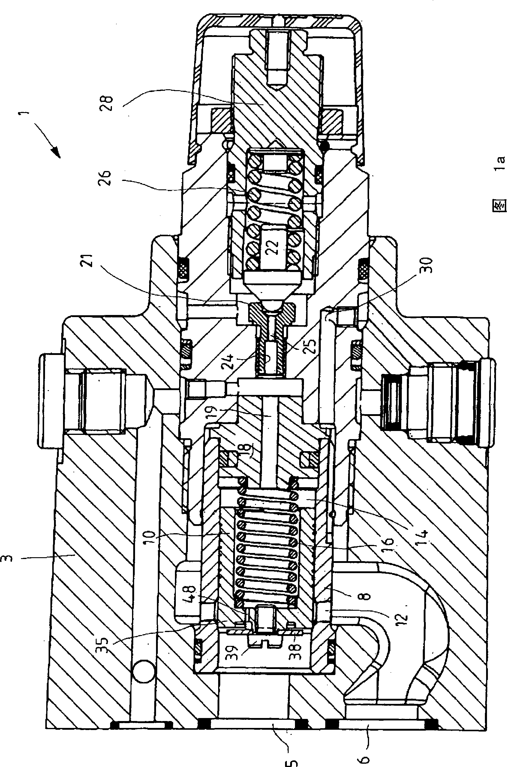
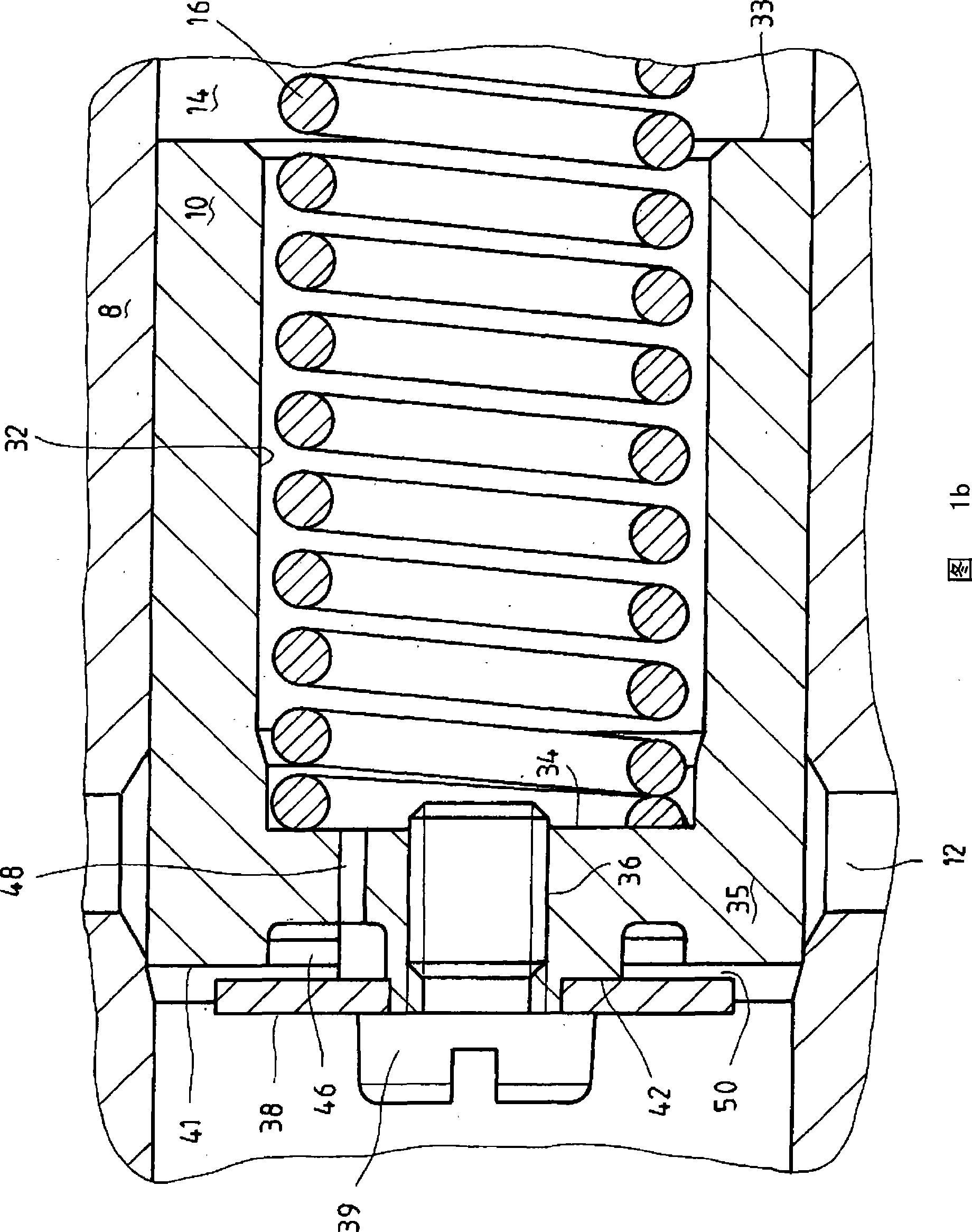
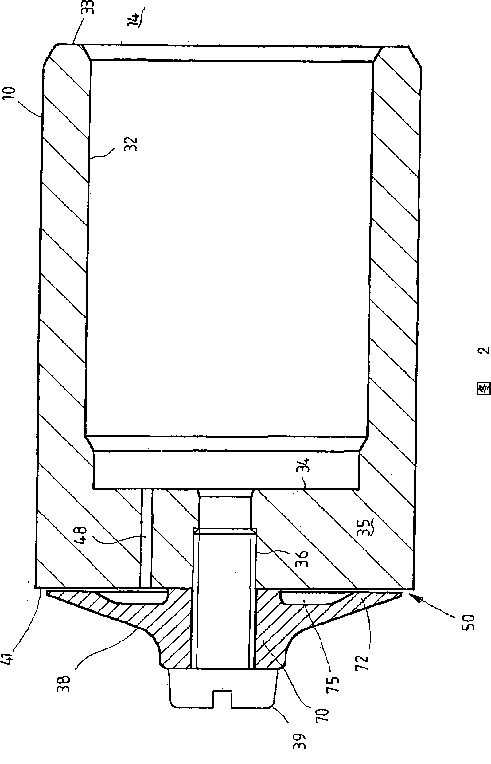
[0070] According to FIG. 1 a , the pilot-operated pressure-limiting valve 1 has a valve body 3 with an inlet connection 5 and a tank connection 6 . A spool is screwed into the valve body 3. The spool is functionally divided into a main stage and a pre-control stage. The main stage essentially consists of a sleeve 8 , in which a main control cone 10 is movably guided. The inner cross section of the sleeve 8 is narrowed in the region of the sleeve 8 facing the inlet connection 5 , so that a valve seat is formed against which the main control cone 10 is pressed in the closed state of the main stage. Radially formed bores 12 are provided in the sleeve 8 , through which pressure medium flows from the inlet connection 5 to the tank connection 6 in the case of an open main stage. The main control cone 10 delimits a spring chamber 14 in a section of the sleeve 8 remote from the inlet connection 5 . In this spring chamber there is a spring 16 which acts on the main control cone 10 i...


PUM


Abstract

A pressure limiting valve has a control element (10) which can be acted on in an opening direction, against a first control face, by a pressure which is to be limited, and which can be acted on in a closing direction by a spring (16) and, against a second control face, by a control pressure prevailing in a control pressure space (14). The pressure prevailing in the control pressure space can be limited by means of a pilot control valve (21). A control fluid can be supplied to the control pressure space through the control element via a control fluid nozzle (48). Upstream of the first control face, a plate (38) is held on the control element. Formed between the plate and the first control face is a gap with a predefined gap dimension. Said gap is situated upstream of the control fluid nozzle.

Description

technical field [0001] The invention relates to a pilot-operated pressure-limiting valve according to the preamble of claim 1 . Background technique [0002] Such a conventional pressure limiting valve is given, for example, in the data sheet RD 25731 / 10.05 or in the data sheet RD 25818 / 08.03 of Bosch Rexroth AG. The main control spool or the main control cone releases the connection between the inlet connection and the tank connection when an adjustable limit pressure is reached. The corresponding main control element (valve cone or valve slide) is acted on in the opening direction by the input pressure on the control surface facing the input connection. A control surface remote from the input interface delimits a control pressure chamber. In the control pressure chamber there is a spring which acts on the main control element in the closing direction. Furthermore, a control pressure is maintained in the control pressure chamber. The control pressure can be adjusted by ...

Claims


Application Information

Patent Timeline
Patent Type & Authority Applications(China)
IPC IPC(8): F16K17/10
CPCF16K17/105G05D16/166G05D16/107Y10T137/7766Y10T137/777Y10T137/7762
Inventor H·沃尔夫格斯
Owner ROBERT BOSCH GMBH
Why Eureka
Try Eureka