Oil pan structure for internal combustion engine

A technology for oil pans and internal combustion engines, which is applied in oil pans, engine lubrication, mechanical equipment, etc., and can solve problems such as oil foaming

Inactive Publication Date: 2009-03-18
TOYOTA JIDOSHA KK
View PDF1 Cites 8 Cited by
  • Summary
  • Abstract
  • Description
  • Claims
  • Application Information

AI Technical Summary

Problems solved by technology

But in this internal combustion engine, because the oil discharged through the drip port of the baffle through the plurality of openings falls on the oil surface in the oil pan, the oil pan Foaming still occurs in the oil in

Method used


Image

  • Oil pan structure for internal combustion engine
  • Oil pan structure for internal combustion engine
  • Oil pan structure for internal combustion engine

Examples


Embodiment Construction

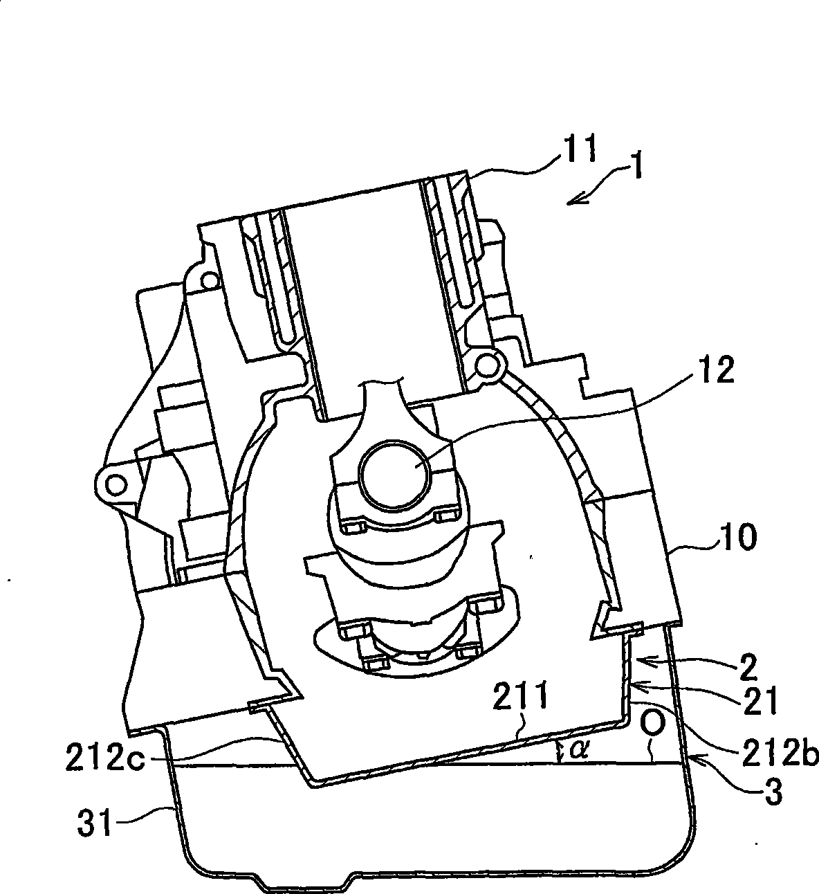
[0015] FIG. 1 shows an example in which an oil pan structure according to an embodiment of the present invention is applied to an inline four-cylinder engine. A trapezoidal trapezoidal frame 10 is attached to the lower surface of the cylinder block 11 of the engine 1 . A crankshaft 12 is rotatably supported between the trapezoidal frame 10 and the cylinder block 11 . In this case, one end of the crankshaft 12 is located on the front side of the engine 1 , and the other end of the crankshaft 12 is located on the rear side of the engine 1 . In other words, the axial direction of the crankshaft 12 coincides with the longitudinal direction of the engine 1 .

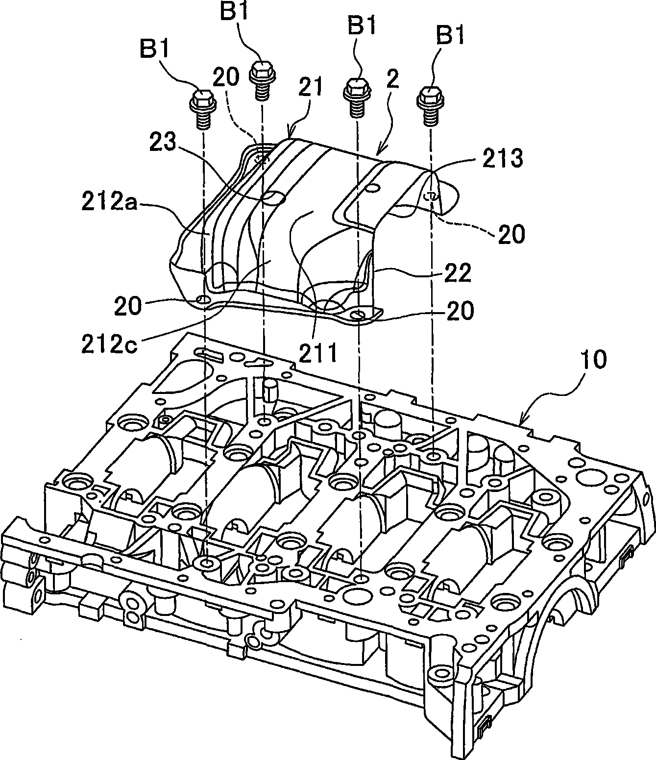
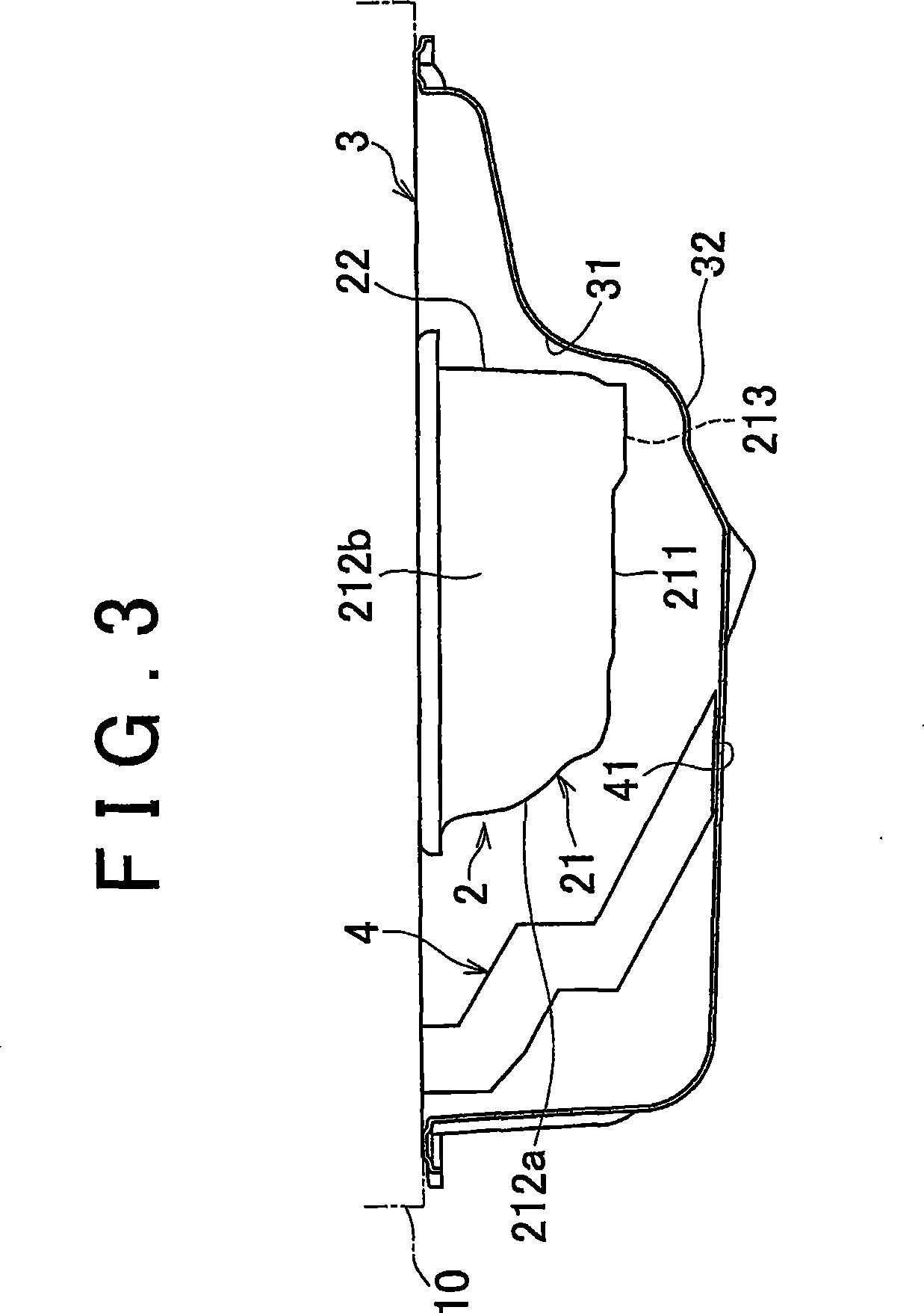
[0016] As shown in FIG. 2 , the baffle plate 2 having a generally rectangular shape in plan view is fixed close to the middle of the lower surface of the trapezoidal frame 10 by bolts B1 passing through bolt holes 20 at four corners. The periphery of the oil pan 3 is connected to the outer periphery of the lower surface of ...


PUM


Abstract

An oil pan structure for an internal combustion engine includes an oil pan (3) and a baffle plate (2) provided inside the oil pan (3) having a storage section (21) for collecting oil that is returned after circulating through the engine to lubricate and cool the engine. The storage section has a generally flat bottom (211) with a generally rectangular shape as viewed in a plan view, and front, left, and right side walls (212a, 212b, and 212c) that extend upward from the bottom (211), The storage section also has an oil drain port (22) through which the oil in the storage section (21) is drained into the oil pan (3) , The opening of oil drain port is near and faces a wall (31) of the oil pan.

Description

technical field [0001] The present invention relates to an oil pan structure of an internal combustion engine, and more particularly, to an oil pan structure that reduces foaming of oil stored in the oil pan. Background technique [0002] Generally, an oil pump is driven by rotation of a crankshaft to draw oil collected in an oil pan through a strainer and deliver the oil under pressure to each component of the internal combustion engine. The oil that has been used to lubricate and cool every part of the internal combustion engine flows back into the oil sump and is recirculated. When the oil flowing back into the oil pan falls on the surface of the oil collected in the oil pan, air bubbles are generated in the collected oil. When oil containing air bubbles is drawn into the strainer, the oil pump may vibrate or an insufficient amount of oil may be supplied to components of the engine. [0003] To deal with this problem, for example, JP-A-2005-120879 describes a convention...

Claims


Application Information

Patent Timeline
Patent Type & Authority Applications(China)
IPC IPC(8): F01M11/00
CPCF01M2011/0041F01M2011/0033F01M2011/0037F01M11/0004F01M11/00F01M11/04
Inventor 川岛孝弘
Owner TOYOTA JIDOSHA KK
Why Eureka
Try Eureka