

Method capable of reducing golf flight speed and golf structure
A golf ball and flying speed technology, applied to ball games, sports accessories, etc., can solve the problems of being unable to practice hard hitting, flying everywhere, high risk of injury, etc., to achieve light weight, improved flight resistance, and easy to pick up ball easy effect
- Summary
- Abstract
- Description
- Claims
- Application Information
AI Technical Summary
Problems solved by technology
Method used
Image

Examples
specific Embodiment approach 2
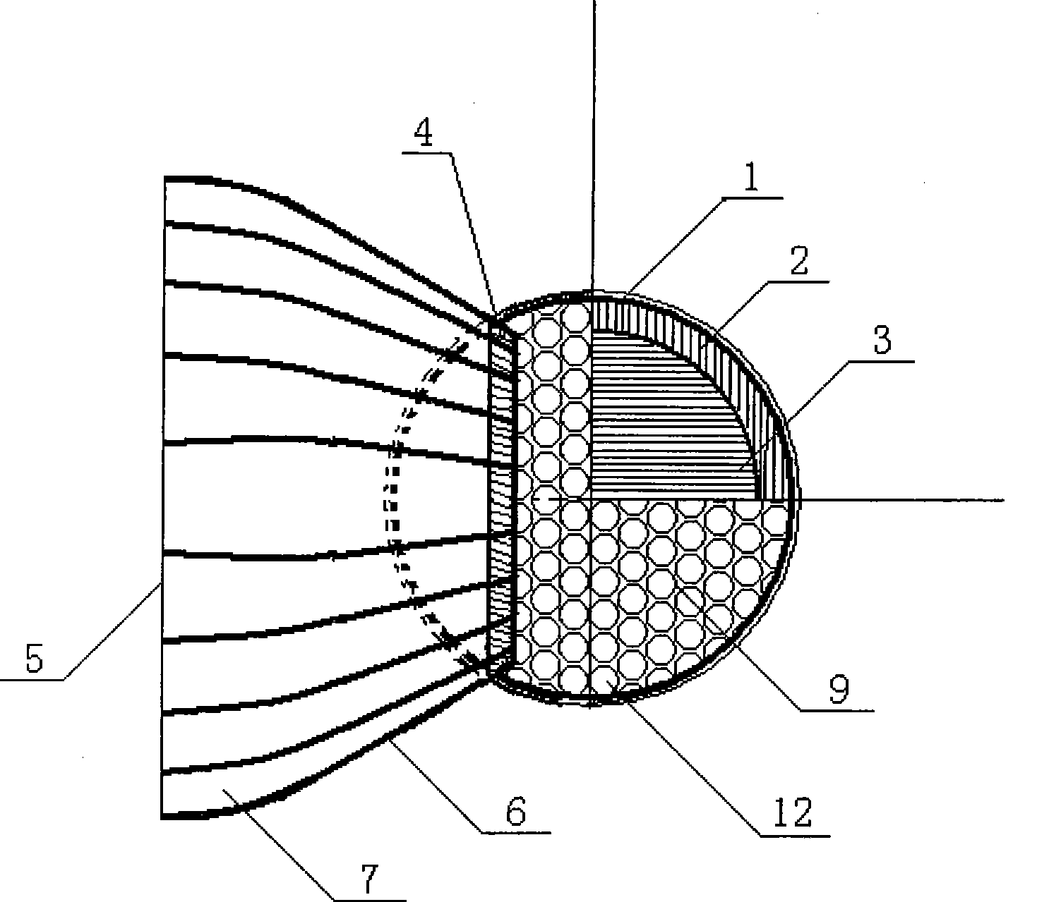
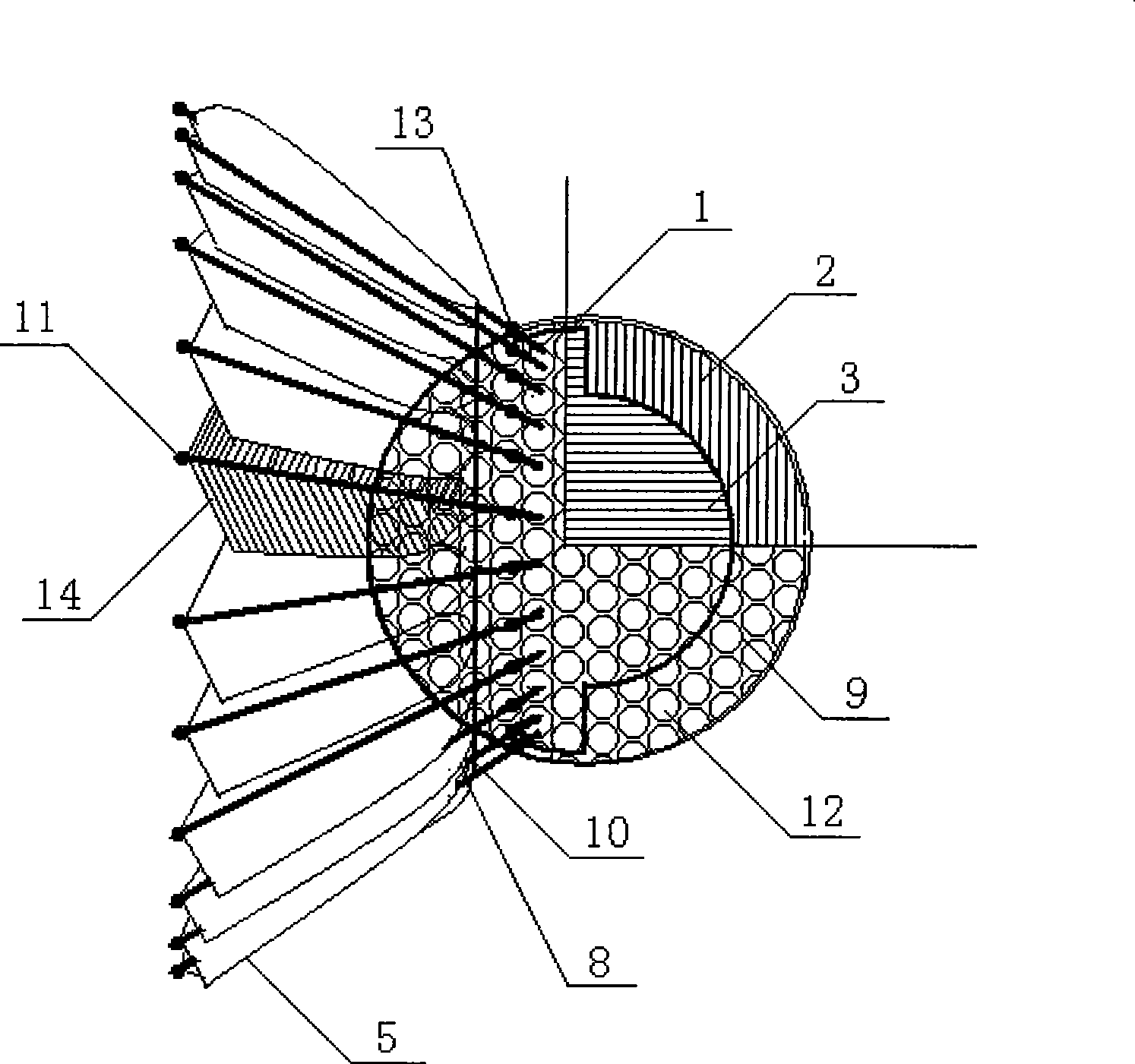
[0026] Such as figure 2 As shown, the ball structure that reduces the flying speed of the golf ball in the present invention includes foamed PU3, cork 2, PU skin 1 and speed reducing device 5. Adopt the material similar to cork 2 in density, and foaming PU3 can be any shape to match the goal that realizes golf ball 9 mass reduction, promptly can be that only the middle layer of hitting surface hemisphere adopts the cork 2 of thickness 8 millimeters, other hemisphere All adopt foaming PU3 and extend to fill the inner side of the cork 2 of the hitting surface hemisphere and glue it with its inner surface. Speed reduction device 5 is made of feather 14, feather root 8, belay rope 10 and spherical head guard 11, and the quantity, length and the angle with central axis of feather 14 all can be adjusted appropriately according to the actual needs of flying speed, adopt 24 lengths in this example The feathers of 40 mm are bundled and arranged in a radial ring at 25° with the cent...
specific Embodiment approach 3
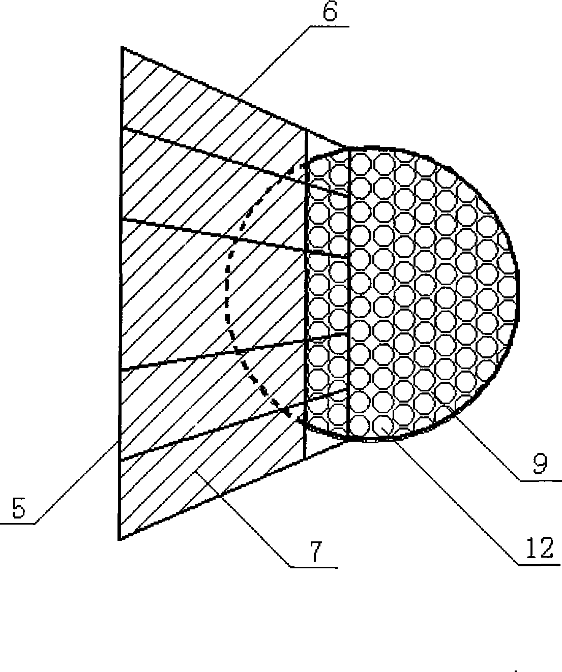
[0027] Such as image 3 As shown: the ball structure for reducing the flying speed of golf balls in the present invention includes a deceleration device 5 and a PU foamed sphere 9. The deceleration device 5 is a radial ring belt that is alternately connected with 12 skeletons 6 and fan surfaces 7 and forms a 20° angle with the central axis. The skeleton 6 of the deceleration device 5 is 38 mm long, and its large-diameter end is flush with the upper end of the 30-mm-diameter sector 7. The 8-mm-long part of the bottom end of the skeleton 6 is not connected to it, and the end of the skeleton 6 is connected to the PU foamed sphere. 9 moldings are integrated, and the outer surface of PU foamed spheroid 9 has the dimple 12 of regular golf ball, and its diameter is controlled at 42.6-42.8 millimeters.
PUM
 Abstract
Description
Claims
Application Information