
Energy-saving fan of spinning frame

A spinning frame and fan technology, applied to spinning machines, machines/engines, mechanical equipment, etc., can solve the problems of increasing the energy consumption burden of enterprises, conflicting spirits of energy-saving and energy-saving, and achieve the effects of pressure loss avoidance, energy saving and dust removal , the effect of reducing power

Inactive Publication Date: 2009-03-25
常熟市鼓风机有限公司
View PDF1 Cites 9 Cited by
  • Summary
  • Abstract
  • Description
  • Claims
  • Application Information

AI Technical Summary

Problems solved by technology

However, the applicant believes that starting from increasing the power of the motor to make up for the pressure loss is not an ideal move. One of the reasons is that it will increase the energy consumption burden of the enterprise; Contrary to the energy-saving spirit

Method used


Image

  • Energy-saving fan of spinning frame
  • Energy-saving fan of spinning frame

Examples


Embodiment

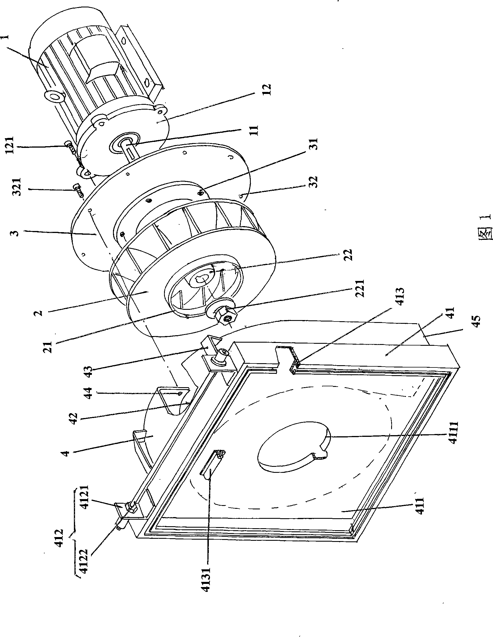
[0021] Please see Fig. 1, the provided motor 1 is a three-phase asynchronous motor, the front cover 12 of the motor 1 is fixed with the first screw 121 and the first screw fixing hole 31 on the rear cover 3, and the first screw 31 on the rear cover 3 is fixed. The second screw fixing hole 32 is used for fixing the second screw 321 to the preset third screw fixing hole 44 on the volute 4 . Centrifugal fan 2 is fixed with the power output shaft 11 of motor 1 by the fan shaft seat 22 in its center, and is also limited by fixing nut 221, and fixing nut 221 is screwed on the shaft head of power output shaft 11, because in The shaft head of the power take-off shaft 11 is processed with external threads. After the rear cover 3 and the volute 4 are fixed, the whole centrifugal fan 2 is integrally located in the cavity 42 of the volute 4 .

[0022] The given volute 4 has a rectangular docking disc 41 in shape, more specifically a square in shape, and the concept of the docking disc 41...


PUM


Abstract

The invention discloses an energy-saving air blower of a spinning machine, pertaining to the technical filed of spinning air blowers. The energy-saving air blower is characterized in that the air blower comprises a rear cover plate and a spiral case provided with a butt-joint plate. The rear cover plate is fixed with a motor front end cover of a motor and also fixed with the spiral case. The centrifugal fan is wholly positioned in a cavity of the spiral case. The energy-saving air blower has the advantages: pressure loss can be effectively avoided so as to reflect the ideal effects of energy conservation and dust elimination. Due to the avoidance of the pressure loss, the power of the motor can be reduced by one time.

Description

technical field [0001] The invention belongs to the technical field of textile fans, and in particular relates to an energy-saving fan for a spinning frame, which is an improvement on the energy-saving fan for a spinning frame in the prior art. Background technique [0002] The concept of the suction mechanism is mentioned in the description of a collection pipe recommended by the Chinese invention patent application publication number CN101070651A applied by the applicant. In the working state, the suction mechanism is also in the working state. Since the tube body of the collecting pipe is hollow, and the nozzle extended on the tube body is connected with the suction mechanism through the pipeline, the centrifugal fan of the suction mechanism Under the action of the negative pressure in the pipe body, the suction groove plays the role of aerodynamic cohesion or aggregation of the fiber strands between the drafting and twisting of the ring spinning roller, and at the same t...

Claims


Application Information

Patent Timeline
Patent Type & Authority Applications(China)
IPC IPC(8): D01H5/66D01H5/72F04D29/42F04D29/62
Inventor 许文元任志达叶妹华潘芳郑驰
Owner 常熟市鼓风机有限公司
Learn More