
Long axis output and electric shaft driven mud pump transmission agent in water

A transmission system and driving technology, which is applied in the direction of mechanically driven excavators/dredgers, etc., can solve the problems that the transmission system is unfavorable to the stability of the central axis, the problem of axial positioning, the shock and torsional vibration of the motor, etc., to achieve Easy replacement of parts, stable operation, and low requirements for axis alignment

Active Publication Date: 2011-07-06
SHANGHAI QIYAO HEAVY IND CO LTD
View PDF0 Cites 0 Cited by
  • Summary
  • Abstract
  • Description
  • Claims
  • Application Information

AI Technical Summary

Problems solved by technology

[0004] 1) In the case of changing working conditions, the irregular deformation and vibration of the bridge, the long-distance power transmission from the motor to the underwater mud pump, etc. will have an impact on the entire system (the irregular deformation and vibration of the bridge will affect the entire transmission system. It is very unfavorable for the center axis and the stability of the operation between the relative moving parts);
[0005] 2) The entire underwater mud pump system needs to be tilted at a certain angle (maximum 50°) together with the bridge frame when it is working. At this time, there are still problems in the axial positioning of each part from the motor to the underwater mud pump;
[0006] 3) The impact problem when the motor starts and the torsional vibration problem that may occur during operation

Method used


Image

  • Long axis output and electric shaft driven mud pump transmission agent in water
  • Long axis output and electric shaft driven mud pump transmission agent in water
  • Long axis output and electric shaft driven mud pump transmission agent in water

Examples


Embodiment Construction

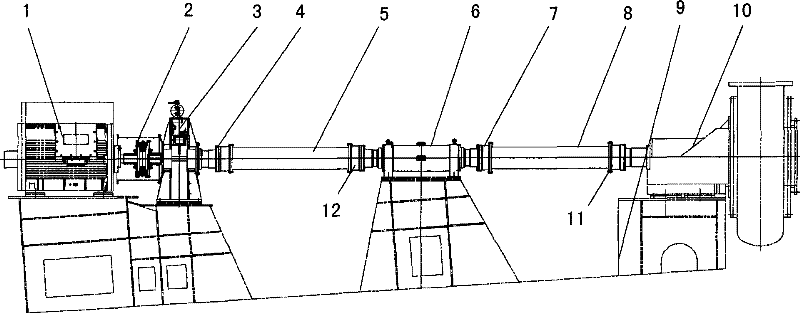
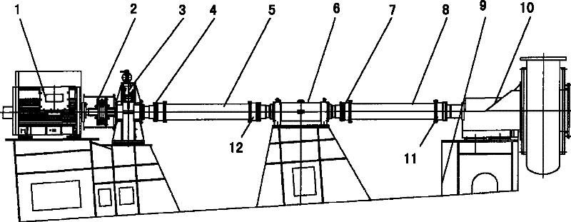
[0024] Such as figure 1 As shown, an embodiment of the electric shaft-driven submerged mud pump transmission system with long shaft output according to the present invention includes a highly elastic coupling 2, a subsea gear box 3, a hollow shaft 5, an intermediate support device 6 and a bridge frame 9 .

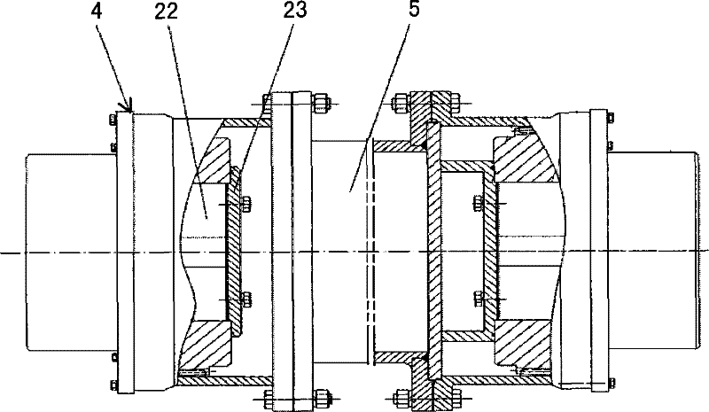
[0025] The electric motor 1 transmits power and rotation speed to the underwater mud pump 10 through the electric shaft driven underwater mud pump transmission system output by the long shaft. The motor 1 is connected to the input shaft of the underwater gearbox 3 through a highly elastic coupling 2 . The output shaft of the underwater gearbox 3 is connected to the left end of the hollow shaft 5 through the drum-shaped tooth coupling 4, the right end of the hollow shaft 5 is connected to the left end of the intermediate support device 6 through the drum-shaped tooth coupling 12, and the right end of the intermediate support device 6 The left end of the hollow shaft 8 is c...


PUM


Abstract

The invention provides a long-shaft output electrical shaft driven type underwater dredge pump transmission system, which is used for transmitting the power and rotating speed of a motor to an underwater dredge pump. The transmission system is characterized in that the transmission system comprises an underwater gearbox, at least two hollow shafts, an intermediate supporting device and a bridge frame; an input shaft of the underwater gearbox is connected with the motor through a high-elasticity coupling; at least two hollow shafts and at least one intermediate supporting device form a long shaft system; in the long shaft system, two ends of the intermediate supporting device are connected with the two hollow shafts through crown gear couplings respectively, and the two hollow shafts are positioned at two ends of the long shaft system respectively; an output shaft of the underwater gearbox is connected with one hollow shaft positioned at one end of the long shaft system through one crown gear coupling, and the other hollow shaft positioned at the other end of the long shaft system is connected with the underwater dredge pump through the other crown gear coupling; and the intermediate supporting device, the underwater gearbox, the motor and the underwater dredge pump are all supported by the bridge frame.

Description

technical field [0001] The invention relates to an underwater mud pump transmission system of a cutter suction dredger. Background technique [0002] The underwater mud pump transmission system is one of the key equipment of the cutter suction dredger. The underwater mud pump transmission system is used to transmit the power of the power machine (mainly including hydraulic motors, electric motors and diesel engines) to the underwater mud pump. At present, the transmission forms of the power system of the underwater dredge pump in the cutter suction dredger mainly include the hydraulic drive type and the electric shaft system drive type. Compared with the former electric shaft system-driven underwater mud pump transmission system, it has the following characteristics: the power source of the system adopts the electric motor, the starting and speed regulation of the electric motor are convenient, the work reliability is high, and the system is easy to operate; the underwater g...

Claims


Application Information

Patent Timeline
Patent Type & Authority Patents(China)
IPC IPC(8): E02F3/88E02F3/90
Inventor 李强严忠胜常震罗龚春全高晓敏董鹏刘渊徐翔江瑞田
Owner SHANGHAI QIYAO HEAVY IND CO LTD
Learn More