
Elastic ground hydrant

A fire hydrant and elastic ground technology, applied in the field of fire hydrants with anti-collision function, can solve the problems of high production cost, complex structure, and no consideration of fire hydrants, etc., and achieve strong pressure resistance, small investment in technical transformation, and low production cost low effect

Inactive Publication Date: 2009-03-25
大丰市供销机械厂有限公司
View PDF1 Cites 3 Cited by
  • Summary
  • Abstract
  • Description
  • Claims
  • Application Information

AI Technical Summary

Problems solved by technology

However, 200720017096.8 also has many defects: 1. It only changes the rigid external structure of the fire hydrant, but does not consider that the internal structure of the fire hydrant is also rigid, so it cannot actually realize the purpose of its own invention; The connector replaces the reducing tube, and the reducing tube not only assumes the role of reducing the diameter, but also assumes the role of installing the one-way valve. After the reducing tube is improved into a universal soft connector, the installation of the one-way valve must be re-solved. 3. According to the common sense of fire hydrant installation, we know that the universal flexible connector part of the invention is buried underground. First, this part will not break due to impact, and there is no need for elastic improvement. The underground universal flexible connector cannot perform elastic function at all because it is filled with soil around; 4. Although the bellows in the universal flexible connector are made of stainless steel bellows, its structure, material and thickness determine its Anti-corrosion, anti-aging, and anti-pressure properties cannot meet the requirements of fire hydrants. Bellows are usually used as telescopic adjustment pipes for thermal expansion and contraction of water pipes in existing tap water supply systems, rather than pressure pipes; 5. Complex structure , high production cost

Method used


Image

  • Elastic ground hydrant
  • Elastic ground hydrant
  • Elastic ground hydrant

Examples


Embodiment Construction

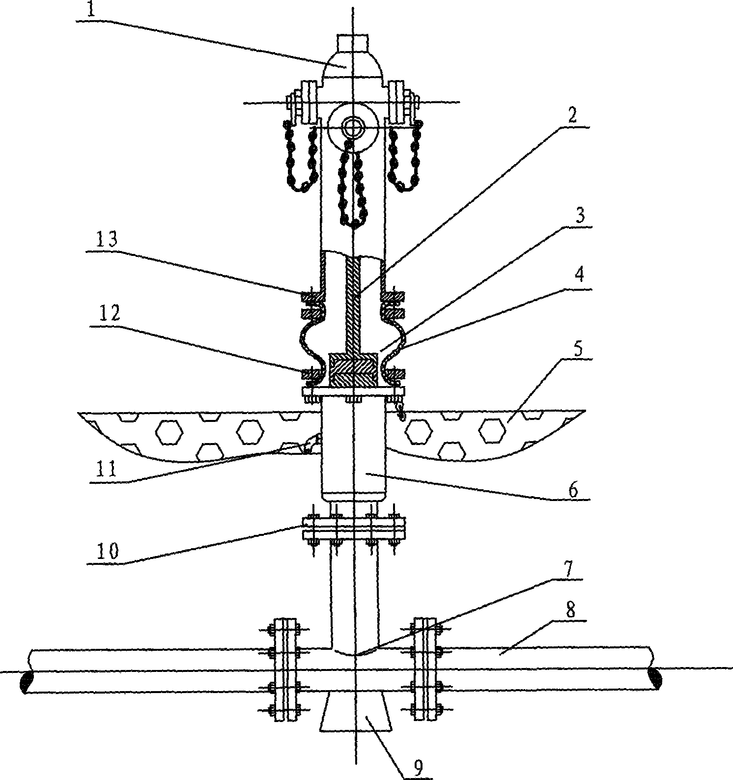
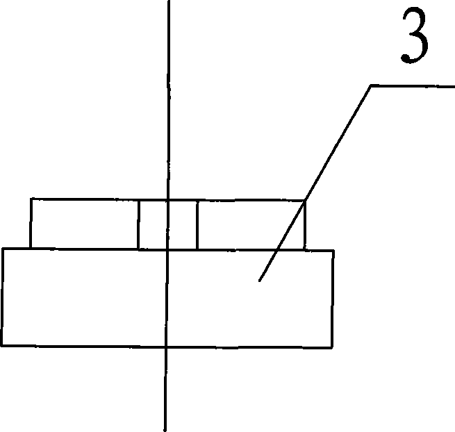
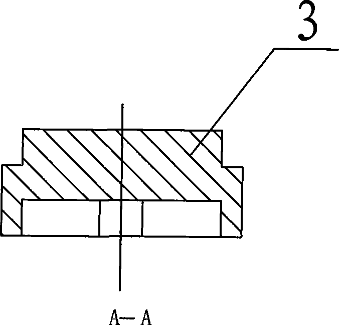
[0013] The elastic above-ground fire hydrant is composed of a fire hydrant body 1, a reducing pipe 6, a fire hydrant connecting water pipe 7, a valve stem 2, a one-way valve, a rubber joint pipe 4 and a rubber cross 3. The fire hydrant body 1 and the rubber joint pipe 4, the rubber joint pipe 4 and the reducer pipe 6, the reducer pipe 6 and the fire hydrant connection water pipe 7 are respectively connected by flanges 13, 12 and 10, and the rubber joints Tube 4 is made of nitrile rubber with lead hair. The rubber ten-byte 3 is made of nitrile rubber with lead hair. It has a raised "cross" fork on its upper surface and a sunken "cross" fork on its lower surface. The valve stem 2 A recessed "cross" fork is provided at the tail end to engage with the upper part of the rubber ten word 3, and a raised "cross" fork is provided at the top of the one-way valve opening mechanism 11 to engage with the lower part of the rubber ten word 3. The top of the valve stem 2 extends to the top o...


PUM


Abstract

The invention provides an elastic aboveground fire hydrant, which relates to a fire hydrant, in particular to a fire hydrant with anticollision function. The fire hydrant at least comprises a fire hydrant body, a reducer pipe, a fire hydrant connecting water pipe, a valve stem and a check valve, and is characterized in that the fire hydrant also comprises a rubber joint pipe and a rubber cross joint; the fire hydrant body and the rubber joint pipe, the rubber joint pipe and the reducer pipe, as well as the reducer pipe and the fire hydrant connecting water pipe are connected through flanges respectively; the check valve is arranged in the reducer pipe; and one end of the valve stem is connected with an opening mechanism of the check valve through the rubber cross joint, and the other end of the valve stem extends to the top of the fire hydrant body. Because both an external structure and an internal structure of the fire hydrant have elasticity, the fire hydrant can effectively counteract destructive power caused by collision, so as to prevent the fire hydrant from breaking.

Description

technical field [0001] The invention relates to a fire hydrant, in particular to a fire hydrant with anti-collision function. Background technique [0002] At present, the above-ground fire hydrant commonly used in China is composed of a fire hydrant body, a reducing pipe, a fire hydrant connecting pipe, a valve stem and a one-way valve. They are respectively connected by flanges, the one-way valve is arranged in the reducing pipe, one end of the valve stem is connected with the opening mechanism of the one-way valve, and the other end extends to the top of the fire hydrant body. When the fire hydrant is installed, the 10 cm end of the fire hydrant body is the dividing line, the fire hydrants of the above part are set above the ground surface, and the rest of the fire hydrants are all buried below the ground surface. Because fire hydrants are generally made of cast iron, if they are affected by external forces, they may break, resulting in a large amount of water loss, and ...

Claims


Application Information

Patent Timeline
Patent Type & Authority Applications(China)
IPC IPC(8): E03B9/02
Inventor 陈瑶吴志荣陈东胜
Owner 大丰市供销机械厂有限公司
Learn More