
Rapid phase discrimination and automatic transmission unit

An automatic transmission and phase identification technology, applied in surveying, wellbore/well components, earth-moving drilling, etc., can solve the problems of difficult precision control, complicated circuits, and the size of the minimum system circuit is not small, and achieve the effect of small size

Inactive Publication Date: 2009-03-25
CHINA NAT OFFSHORE OIL CORP +1
View PDF5 Cites 2 Cited by
  • Summary
  • Abstract
  • Description
  • Claims
  • Application Information

AI Technical Summary

Problems solved by technology

The phase detection of analog technology is mainly to extract the time base difference of the zero-crossing point of the two signals with analog technology. The main problems are that the accuracy is difficult to control and the circuit is relatively complicated.
At present, computing technology phase identification is mainly based on related computing methods. The main problem is that it needs to build an embedded operating system. The smallest system is quite large in terms of circuit scale.

Method used


Image

  • Rapid phase discrimination and automatic transmission unit
  • Rapid phase discrimination and automatic transmission unit
  • Rapid phase discrimination and automatic transmission unit

Examples


Embodiment Construction

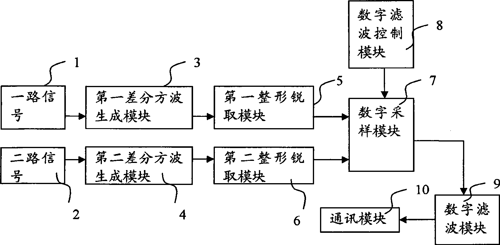
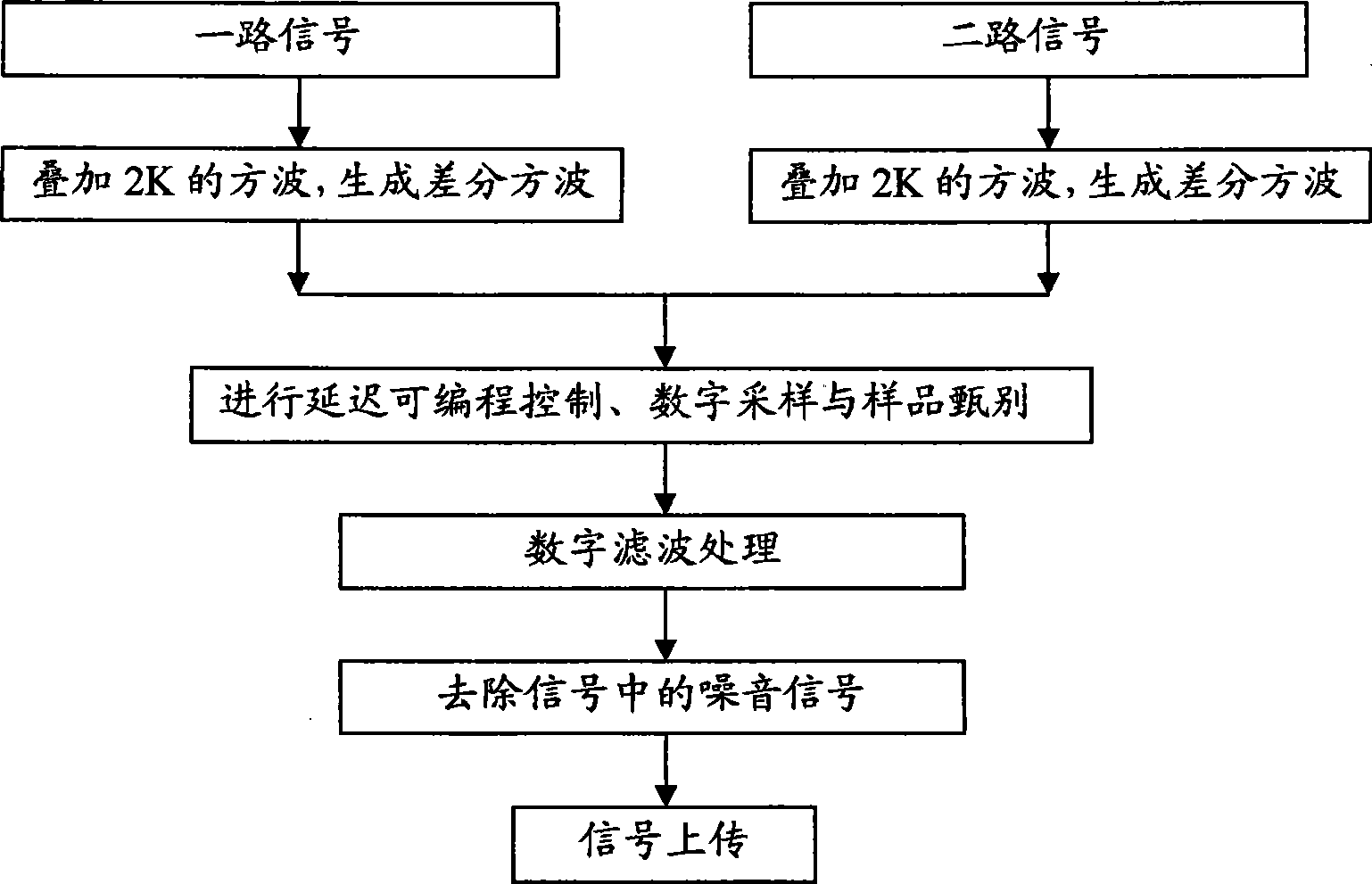
[0020] like figure 1 , 2 As shown, the present invention includes: a first differential square wave generation module 3, a second differential square wave generation module 4, a first shaping sharpening module 5, a second shaping sharpening module 6, a digital sampling module 7, and a digital filtering control module 8. A digital filter module 9 and a communication module 10 . The process of signal transmission and processing is as follows: figure 2 As shown, specifically:

[0021] After a signal 1 passes through the first differential square wave generation module 3, it is superimposed with a 2k square wave, and the superimposed signal is transmitted to the first shaping and sharpening module 5, which is used for the first shaping and sharpening module 5. Shaping and precise edge sharpening are performed, and the first shaping and sharpening module 5 generates a synchronous narrow pulse, and then the narrow pulse is transmitted to the digital sampling module 7 .

[0022]...


PUM


Abstract

The invention discloses a quick phase demodulation and automatic transmission unit, which comprises a first differential square wave generating module (3), a second differential square wave generating module (4), a first shaping acute access module (5), a second shaping acute access module (6), a digital sampling module (7), a digital filter control module (8), a digital filter control module (9)and a communication module (10). The quick phase demodulation and automatic transmission unit not only can quickly output phase difference at a speed of microsecond level, but also can realize accuracy without upper limit.

Description

technical field [0001] The invention relates to an FPGA single-chip phase discrimination and communication unit used for an array induction well logging instrument. Background technique [0002] In the FPGA (Field Programmable Gate Array) single chip of the current array induction logging tool, the phase detection technology mainly includes analog technology phase detection and calculation technology phase detection. The phase detection of analog technology is mainly to extract the time base difference of the zero-crossing point of the two signals with analog technology. The main problems are that the accuracy is difficult to control and the circuit is relatively complicated. At present, computing technology phase identification is mainly based on related computing methods. The main problem is that it needs to build an embedded operating system, and the smallest system is quite large in terms of circuit scale. Contents of the invention [0003] The technical problem to be...

Claims


Application Information

Patent Timeline
Patent Type & Authority Applications(China)
IPC IPC(8): E21B49/00E21B47/00
Inventor 张瑞
Owner CHINA NAT OFFSHORE OIL CORP
Learn More