Supercharge Your Innovation With Domain-Expert AI Agents!

Method for making a composite airfoil

A technology of airfoils and composite wings, which is applied to pump components, household components, engine components, etc., and can solve problems such as corrosion and erosion of airfoils

Inactive Publication Date: 2009-03-25
GENERAL ELECTRIC CO
View PDF4 Cites 4 Cited by
  • Summary
  • Abstract
  • Description
  • Claims
  • Application Information

AI Technical Summary

Problems solved by technology

Such flushing can corrode and attack the metallic material of the airfoil

Method used


Image

  • Method for making a composite airfoil
  • Method for making a composite airfoil
  • Method for making a composite airfoil

Examples


Embodiment Construction

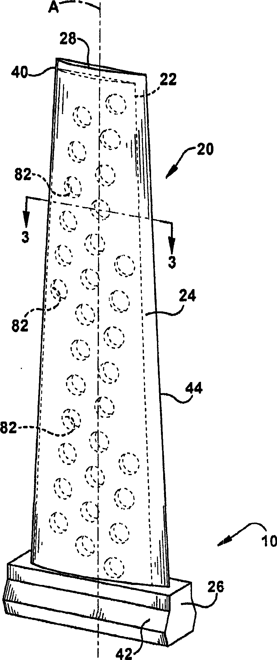
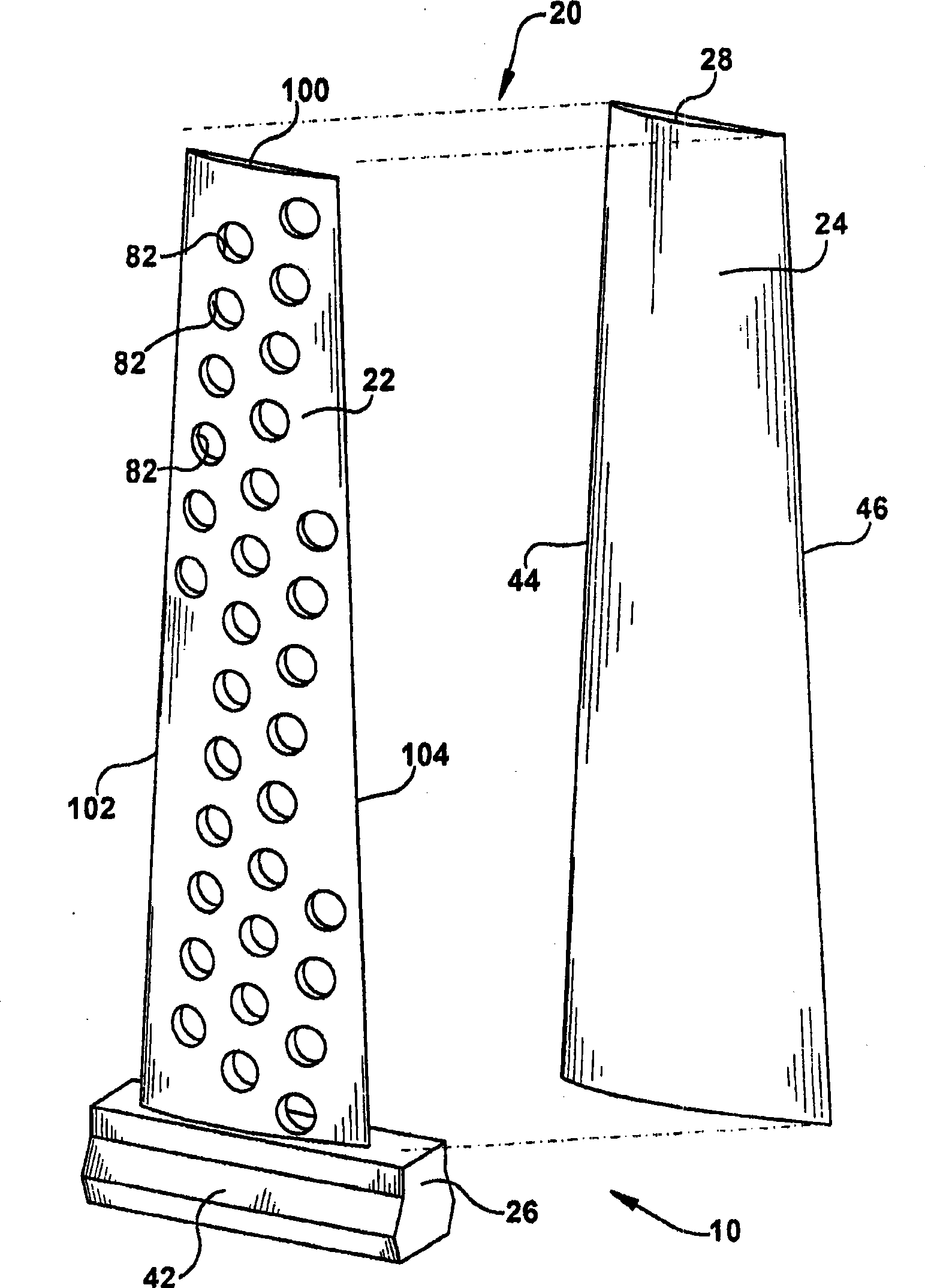
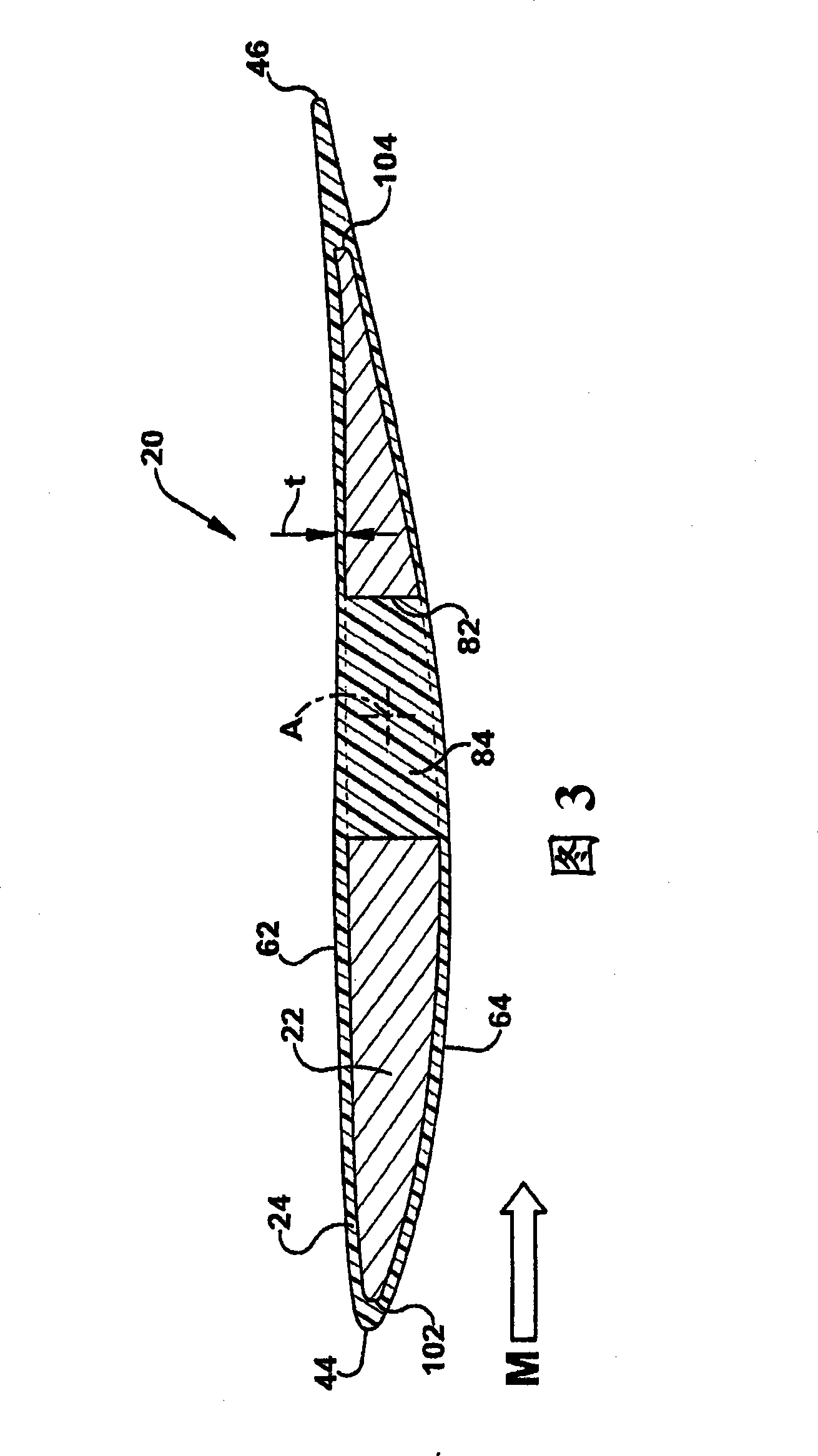
[0020] According to one aspect of the present invention, figure 1 The composite airfoil 20 shown in is part of a blade 10 for a gas turbine used in power generation applications. It should be appreciated that the composite airfoil 20 of the blade 10 in various aspects of the invention may be in the form of a compressor blade, vane or turbine blade and may be used in steam turbine, gas turbine or wind turbine applications. According to one aspect, the composite airfoil 20 of the blade 10 includes a core 22 and a plastic airfoil portion 24 completely surrounding and encapsulating the core.

[0021] Composite airfoil 20 is made in a unique fashion from at least two different materials. “Composite” as used herein is defined as having a plastic material form the polished airfoil portion 24 positioned over a relatively rigid structural material (eg, metal or ceramic) of the core 22 . The term "plastic" is defined as being able to melt at a temperature relatively below the melting ...


PUM


Abstract

A method of manufacturing a composite airfoil includes the step of providing a core (22) made of a metal or ceramic material. A plastic airfoil portion (24) is molded to envelope at least a portion of the core (22).

Description

technical field [0001] The invention generally relates to turbomachinery. In particular, the invention relates to the manufacture of turbomachinery airfoils having components formed from different materials. Background technique [0002] Turbines can take many forms or serve a variety of purposes. These forms and uses may include steam turbines for power generation, gas turbines for power generation, gas turbines for aircraft propulsion, and wind turbines for power generation. [0003] In a gas turbine there are typically many rotating blades and stationary vanes. The blades and vanes are arranged in alternating circumferential arrays spaced longitudinally along the turbine. Each blade and vane includes an airfoil portion attached to a mounting portion. [0004] Conventional gas or steam turbine blade or vane designs typically have their airfoil portions made entirely of alloys of metals such as titanium, aluminum, or stainless steel. Conventional gas or steam turbine c...

Claims


Application Information

Patent Timeline
IPC IPC(8): F01D5/14F01D9/02B29C45/14
CPCF04D29/324F05D2300/43F04D29/023F05D2300/603Y02T50/673B29C45/14778B29C45/14311F04D29/388Y02T50/672B29K2705/00B29L2031/7504B29C2045/14327F05D2300/21F01D5/147B29C70/72B29C70/70F05D2260/95Y10T29/49337Y02T50/60
Inventor J·L·莫罗索T·R·蒂普顿
Owner GENERAL ELECTRIC CO
Features
  • R&D
  • Intellectual Property
  • Life Sciences
  • Materials
  • Tech Scout
  • Unparalleled Data Quality
  • Higher Quality Content
  • 60% Fewer Hallucinations
Learn More