Laser beam M* factor matrix measuring method and measuring instrument

A factor matrix and laser beam technology, applied in the field of laser beam quality analysis, can solve the problems of large difference in spot energy density, limiting measurement accuracy and application range, etc.

Inactive Publication Date: 2009-03-25
SICHUAN UNIV
View PDF0 Cites 18 Cited by
  • Summary
  • Abstract
  • Description
  • Claims
  • Application Information

AI Technical Summary

Problems solved by technology

Due to the large difference in energy density between the largest spot and the smallest spot appearing on the same CCD surface, it is easy to cause the CCD to be saturated at the smallest spot and the gray value of the image formed by the largest spot on the CCD is still low. Limits the accuracy and scope of measurement

Method used


Image

  • Laser beam M* factor matrix measuring method and measuring instrument
  • Laser beam M* factor matrix measuring method and measuring instrument
  • Laser beam M* factor matrix measuring method and measuring instrument

Examples


Embodiment 1

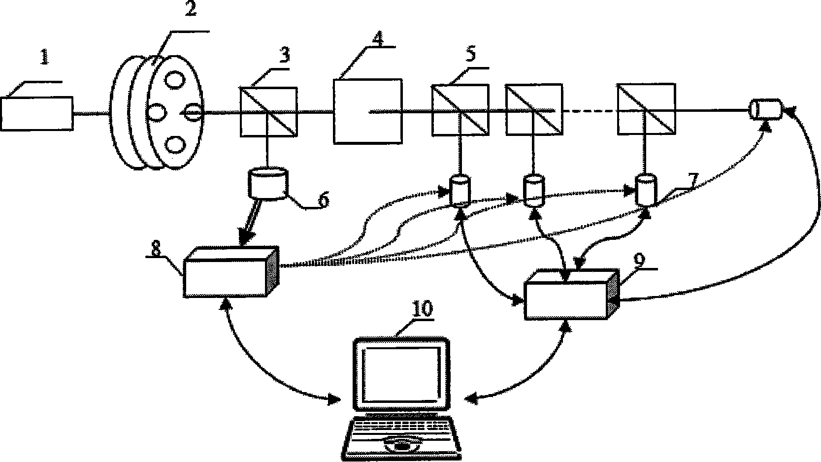
[0053] In this embodiment, the laser beam M 2 The structure of the factor matrix real-time measuring instrument is as figure 1 As shown, the linear attenuator with adjustable attenuation factor 2, the beam splitter 3, the focuser with adjustable focal length 4, the beam splitter group 5, the photodetector 6, the synchronization controller 8, the charge coupled device group 7, the router 9 and computer 10, there are 9 beam splitters in beam splitter group 5, and 10 charge coupled devices (CCD) in charge coupled device group 7.

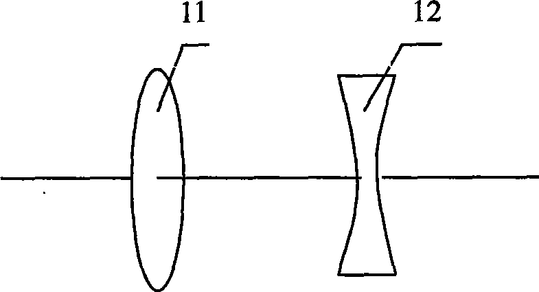
[0054] The linear attenuator 2 with adjustable attenuation multiple is selected as GCC-3010 (produced by Daheng Optoelectronics); the beam splitter 3 is a low-reflectivity mirror with a reflectivity of 5%; the focuser 4 with adjustable focal length is made of A convex lens 11 and a concave lens 12 are combined (such as image 3 As shown), the focal length of the convex lens and the concave lens are both 20cm (which can meet most measurement needs), and the...

Embodiment 2

[0064] This embodiment uses the laser beam M described in embodiment 1 2 The factor matrix real-time measuring instrument performs M on the laser output from laser 1 2 Factor matrix measurement. Laser beam M 2 The workflow of the factor matrix real-time measuring instrument Figure 4 , Laser beam M 2 For the procedure of the factor matrix measurement method, see Figure 5 .

[0065] 1. Warm-up and self-check

[0066]The preheating time is 5 minutes. After preheating, the measuring instrument is allowed to perform self-test.

[0067] 2. Input and prediction of initial parameters

[0068] The initial parameters are: the input wavelength is 652nm and the focal length of the focuser 4 is 20cm.

[0069] After predicting the amount, the program gives the reference adjustment parameters: the distance d between the convex lens and the concave lens in the focuser 4 is 10 cm, and the attenuation multiple of the linear attenuator 2 is 1000 times. The adjustment of the exposure time of each C...


PUM


Abstract

The invention discloses a method for measuring an M<2> factor array of a laser beam, which comprises the following steps: (1) at least ten spot diagrams of the measured laser at different optical paths simultaneously are obtained through the synchronous measurement of at least ten charge-coupled devices; (2) the spot diagrams obtained in step (1) are processed through a computer to obtain an M<2> factor of the measured laser under a laboratory system of coordinates: Mx<2> and My<2>; (3) the spot diagrams obtained in step (1) are rotated with an angle of alpha through the computer, and then an M<2> factor after the rotation is obtained according to the processing method in step (2): Mx1<2> and My1<2>; and (4) the M<2> factor array of the measured laser is calculated according to the M<2> factor under the laboratory system of coordinates, the M<2> factor after the rotation, and the rotation angle alpha. A measuring instrument for the method consists of a linear attenuator, a beam splitter, a focalizer, a beam splitter group, a photoelectric detector, a synchronous controller, a charge-coupled device group, a router and a computer.

Description

Technical field [0001] The invention belongs to the field of laser beam quality analysis, and particularly relates to a laser beam M 2 Matrix analysis method and analysis instrument. Background technique [0002] The quality of the laser beam directly affects the application of the laser. Therefore, qualitative and quantitative analysis of laser beam quality must be done. In the early 1990s, Siegman proposed to adopt M 2 The factor describes the quality of the laser beam. This recommendation was adopted by the International Organization for Standardization, and in 1991 the draft standard ISO / TC172 / SC9 / WG1 based on this recommendation was published. In 2005, the International Organization for Standardization announced the latest version of M 2 Factor measurement standard (ISO 11146). [0003] M 2 The factor describes the difference between the actual beam and the ideal fundamental mode Gaussian beam, and its measurement and calculation are based on the measured value of the beam w...

Claims


Application Information

Patent Timeline
Patent Type & Authority Applications(China)
IPC IPC(8): G01J1/00
Inventor 冯国英邓国亮李玮周寿桓
Owner SICHUAN UNIV
Why Eureka
Try Eureka