Powerline fault traveling wave head precision positioning method based on S-transform
What is Al technical title?
Al technical title is built by PatSnap Al team. It summarizes the technical point description of the patent document.
A technology for precise positioning and transmission lines, applied in the direction of fault location, complex mathematical operations, etc., can solve the problems of inaccurate sampling points and inaccurate location of wave head time
Active Publication Date: 2009-03-25
KUNMING UNIV OF SCI & TECH
View PDF0 Cites 22 Cited by
Summary
Abstract
Description
Claims
Application Information
AI Technical Summary
This helps you quickly interpret patents by identifying the three key elements:
Problems solved by technology
Method used
Benefits of technology
Problems solved by technology
In the engineering application of traveling wave head detection, the cubic B-spline wavelet is considered to be a wavelet base with good signal singularity detection ability, and mathematical morphology also constructs unique flat structural elements with different origins, co
Method used
Image
Click on the blue label to locate the original text in one second.
Reading with bidirectional positioning of images and text.
Examples
Embodiment 1
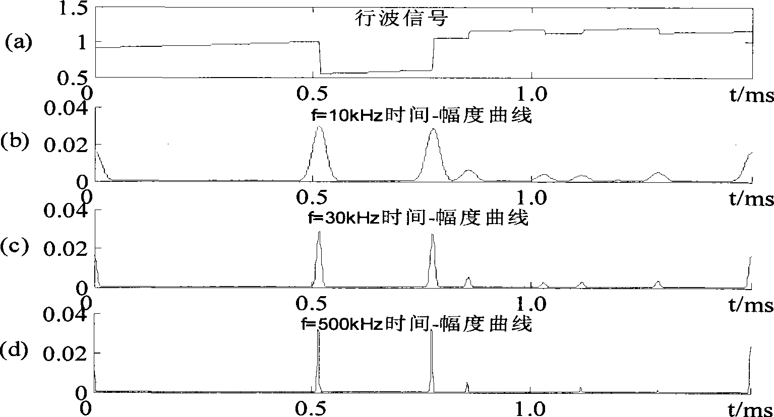
[0073] (1) Obtain the traveling wave data source of the transmission line fault: When the line fails, the fault traveling wave analysis device is activated to perform fast and high sampling rate (1MHz) wave recording, and the traveling wave data file is truncated, see Figure 4 (a) Curve, select 1.5ms data time window before and after the fault;
[0074] (2) Perform S transformation on the original truncated data selected in step (1) according to equations (8), (9), (10):
[0075] S [ m , n ] = Σ k = 0 N - 1 X [ n + k ] e - 2 π 2 k ...
Embodiment 2
[0085] In this example, there is no noise interference, and the steps to distinguish between wave heads and noise may not be performed, but traveling wave heads of different polarities are included.
[0086] (1) Obtain the fault traveling wave data source of the transmission line: when the line fails, the fault traveling wave analysis device is activated to perform fast and high sampling rate (1MHz) wave recording;
[0087] (2) Truncate the traveling wave data file, see figure 1 (a) Curve, select 1.5ms data time window before and after the fault;
[0088] (3) Calculate according to the same formulas (8), (9) and (10) as in Example 1, to obtain the S transformation result matrix S[m, n] of the original truncated data selected in step (2), and its elements Take the modulus value to obtain the S transform modulus matrix;
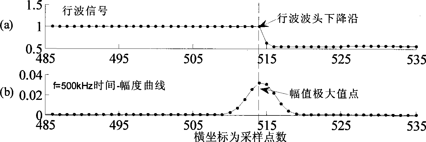
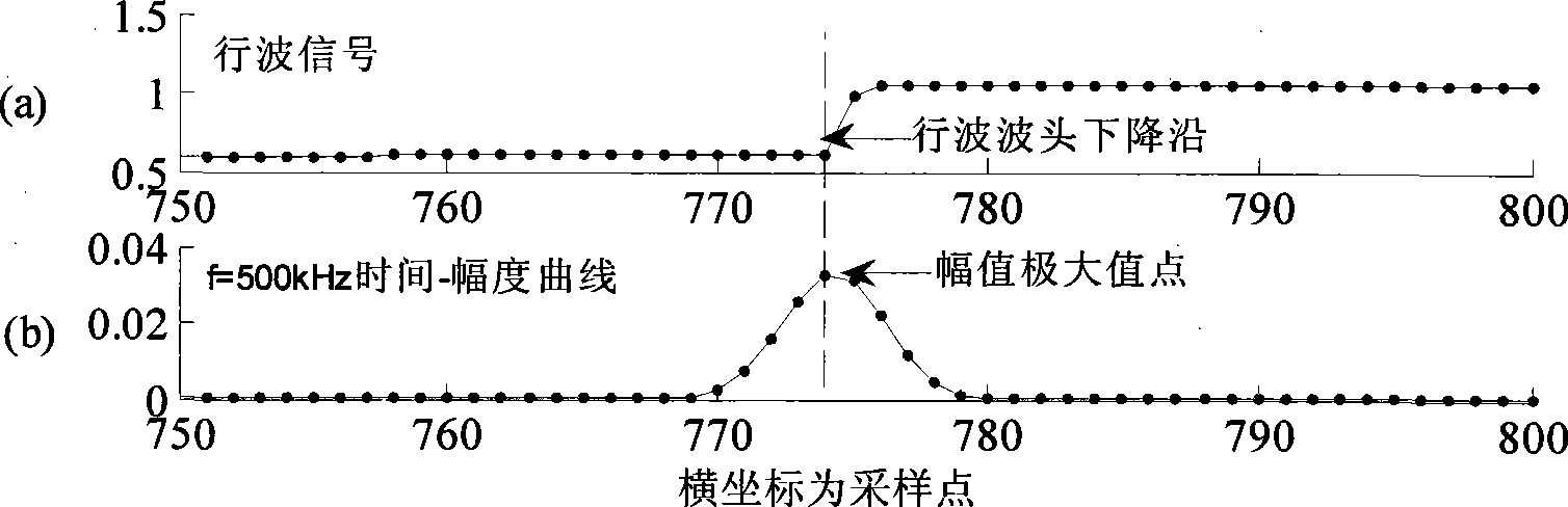
[0089] (4) Select the 750th, 45th, and 15th rows of the S transform modulus matrix in step (3). According to the same formula (12) as in Example 1, the frequency ...
PUM
Abstract
The invention relates to an S-transform based transmission fault traveling wave heat positioning method and belongs to the technical field of relay protection of a power system. The method comprises the following steps: carrying out data window truncation of a fault traveling wave signal and S-transform of a small quantity of key data, with amplitude-time-frequency information of the traveling wave signal expressed by an S-transform modular matrix; basically filtering influence of noise and initially determining the position of a head of the traveling wave according the different performance of the head of the traveling wave and the noise in different frequency range; intensively inspecting an amplitude-time graph at a point of the highest frequency in which a point of maximum amplitude represents a point of the most intensive vibration of the head of the traveling wave, namely a point of the arrival time of the head of the traveling wave; and marking polarity information of the head of the traveling wave according to the characteristics of an original signal near the point of the arrival time of the head of the traveling wave. Principle analysis and simulation data and engineering data verification show that the method can accurately indicate the arrival time of the head of the fault traveling wave and is advantageous to the prior method.
Description
Technical field [0001] The invention relates to a method for accurately positioning the traveling wave head of a transmission line fault based on S transformation, and belongs to the technical field of power system relay protection. Background technique [0002] Compared with the traditional fault location technology based on power frequency quantity, the fault location technology based on traveling wave [1-6] The accuracy is high, and it is not easily affected by the system operation mode, transition resistance, CT saturation, and line distributed capacitance. Therefore, it has become one of the hot research topics in the field of relay protection. The precise positioning of the arrival time of the traveling wave head is one of the key technologies to improve the accuracy of ranging. Wavelet analysis [4,7,8] , Mathematical Morphology [9-10] And the combination of wavelet and mathematical morphology [12] The application of the method in the positioning of the arrival time of the ...
Claims
Application Information
Patent Timeline
Application Date:The date an application was filed.
Publication Date:The date a patent or application was officially published.
First Publication Date:The earliest publication date of a patent with the same application number.
Issue Date:Publication date of the patent grant document.
PCT Entry Date:The Entry date of PCT National Phase.
Estimated Expiry Date:The statutory expiry date of a patent right according to the Patent Law, and it is the longest term of protection that the patent right can achieve without the termination of the patent right due to other reasons(Term extension factor has been taken into account ).
Invalid Date:Actual expiry date is based on effective date or publication date of legal transaction data of invalid patent.