Supercharge Your Innovation With Domain-Expert AI Agents!

Lens coating jig and lens coating method

A technology of lenses and fixtures, applied in optics, instruments, optical components, etc., can solve problems such as inaccurate lens coating positions, affecting the imaging quality of optical products, reducing the yield rate of optical products, etc., and achieve good coating effects

Inactive Publication Date: 2009-03-25
HONG FU JIN PRECISION IND (SHENZHEN) CO LTD +1
View PDF0 Cites 3 Cited by
  • Summary
  • Abstract
  • Description
  • Claims
  • Application Information

AI Technical Summary

Problems solved by technology

[0004] However, since the position of the lens coating is limited by the position of the through holes of the upper tray and the lower tray, once the position of the through hole does not match the position of the lens to be coated, it is easy to cause inaccurate coating position of the lens, which may cause the part of the lens that should be coated to be uncoated. upper layer
In addition, since the upper tray and the lower tray have a certain thickness, that is to say, the through hole has a certain depth, due to the well depth effect, the part of the lens close to the inner surface of the through hole may not be coated with a film of a predetermined thickness, resulting in lens Uneven distribution of film thickness at the coating part
The optical phenomena such as reflection, transmission or refraction produced by the light in the parts that should be coated but not coated or in the parts with uneven film thickness distribution are different from those in the parts with normal film thickness. Inaccurate or uneven coating thickness will affect the imaging quality of optical products and reduce the yield of optical products

Method used


Image

  • Lens coating jig and lens coating method
  • Lens coating jig and lens coating method
  • Lens coating jig and lens coating method

Examples


Embodiment Construction

[0020] The lens coating fixture and the lens coating method of the technical solution will be further described in detail below in conjunction with the accompanying drawings.

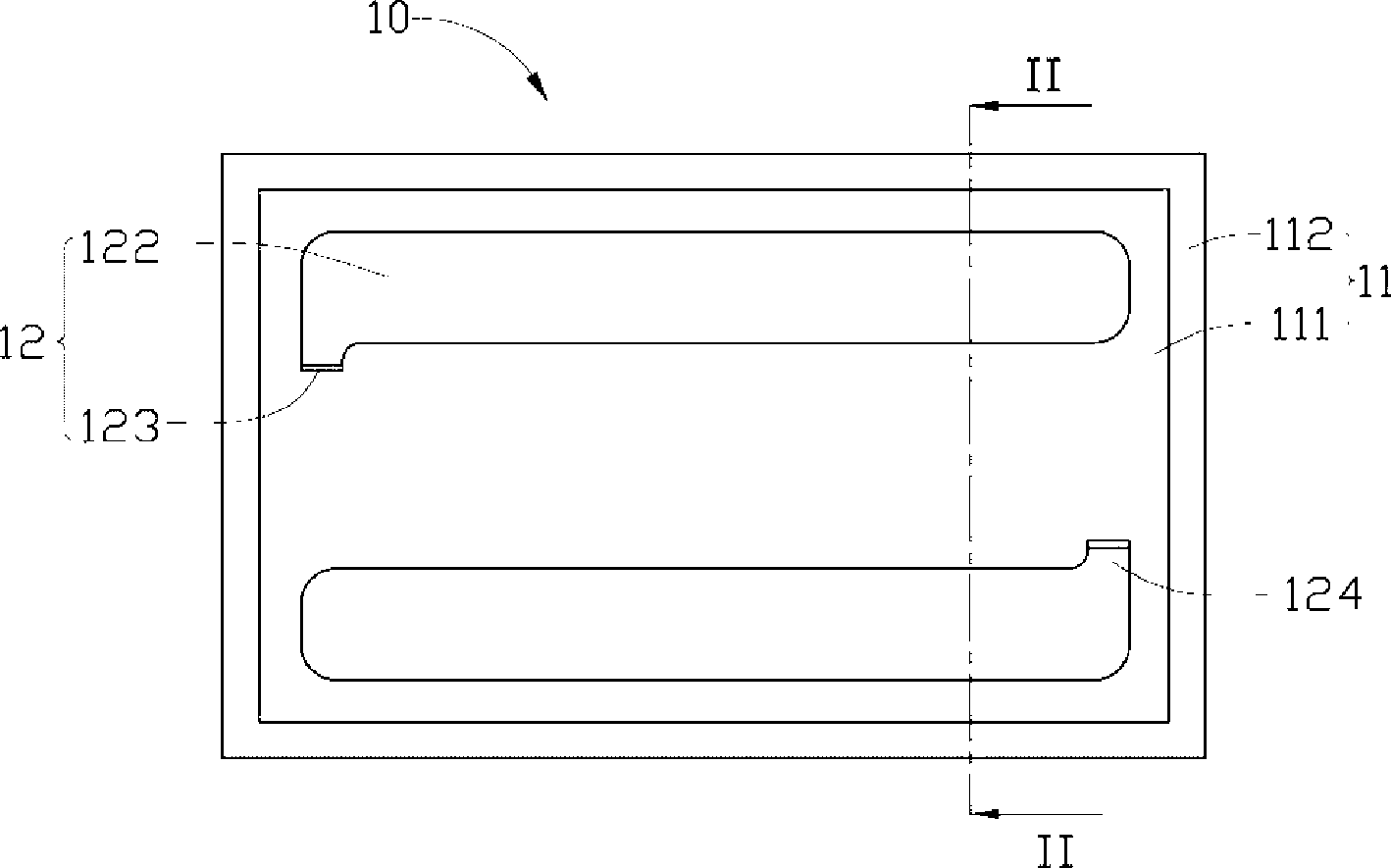
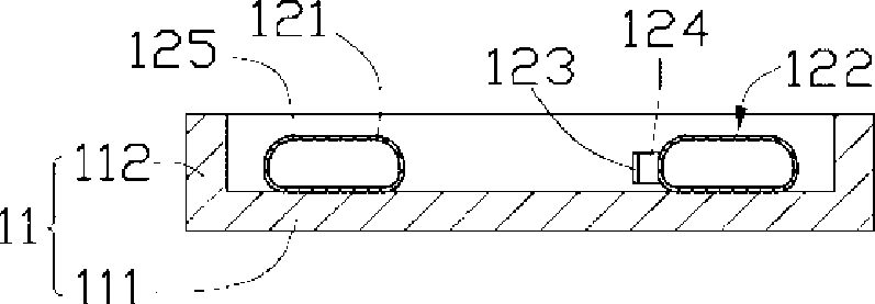
[0021] Please also refer to figure 1 and figure 2 The lens coating jig 10 provided by the first embodiment of the technical solution includes a frame body 11 and two holders 12 . The frame body 11 is composed of a bottom wall 111 and a side wall 112 , and the frame body 11 is used to support two holders 12 . The two holders 12 are placed oppositely in the frame body 11 and contact the bottom wall 111 , and the two holders 12 are used to cooperate and hold the lens.

[0022] Each holder 12 includes a capsule 122 surrounded by an elastic wall 121 and a sealing body 123 . The capsule body 122 is a strip-shaped hollow object having at least one opening 124 and an inner cavity 125 . The inner cavity 125 is used to accommodate fluid, and the at least one opening 124 is a channel for filling the inner cav...


PUM


Abstract

The invention provides a lens coating fixture. The fixture comprises a frame body and at least two holding pieces arranged in the frame body oppositely, each holding piece comprises a bag body provided with at least one opening and enclosed by the elastic wall and a sealing body used for sealing the opening, and the bag body is used for accommodating certain amount of fluid, so that the at least two holding pieces can fit mutually to hold lens. The lens coating fixture in the technical proposal does not affect the part to be coated of the lens and can ensure that the lens have good coating effect. The technical proposal also provides a lens coating method.

Description

technical field [0001] The invention relates to lens coating technology, in particular to a lens coating jig and a lens coating method. Background technique [0002] With the development of optical products, the scope of application of optical lenses is becoming wider and wider. Correspondingly, the industry adopts various methods to manufacture optical lenses to meet the market demand for optical lenses of different specifications (see "Fabrication of Diffractive Optical Lens for Beam splitting Using LIGA Process", Mechatronics and Automation, Proceedings of the 2006 IEEE International Conference on, pp.1242-1247, 2006.06). Generally speaking, the manufactured optical lenses need to undergo subsequent processing to obtain good properties suitable for the application. [0003] The coating process is one of the important steps in the subsequent processing. Coating refers to coating a single-layer or multi-layer film on the surface of the lens by physical or chemical method...

Claims


Application Information

Patent Timeline
Patent Type & Authority Applications(China)
IPC IPC(8): G02B1/10B05C3/09B05C13/02
Inventor 凌维成
Owner HONG FU JIN PRECISION IND (SHENZHEN) CO LTD
Features
  • R&D
  • Intellectual Property
  • Life Sciences
  • Materials
  • Tech Scout
  • Unparalleled Data Quality
  • Higher Quality Content
  • 60% Fewer Hallucinations
Learn More