Winding-type vacuum coater

A vacuum coating and winding technology, applied in vacuum evaporation coating, sputtering coating, ion implantation coating, etc., can solve the problems of complex equipment structure, unsatisfactory tension control effect, high cost, etc.

Inactive Publication Date: 2010-08-11
袁惠芬
View PDF3 Cites 29 Cited by
  • Summary
  • Abstract
  • Description
  • Claims
  • Application Information

AI Technical Summary

Problems solved by technology

However, in the existing winding-type vacuum coating equipment, the winding device is generally an active device, that is, an active unwinding roller device and an active winding roller device. Gradually decreases, and the diameter of the material roll coiled on the winding roller increases gradually. If the rotation speed of the winding device is constant, the tension on the surface of the substrate will change with the change of the material roll diameter, which will cause the film layer to be unstable. Uniformity, affecting the coating effect
In order to avoid the defect of uneven film layer caused by the change of substrate tension, at present, magnetic powder clutches and tension sensor shafts with photoelectric or radio detection are generally used to adjust the rotational speed of the winding device, so as to achieve tension control. However, this results in complex structure and high cost of the equipment, and due to the response delay and response error of the sensing circuit, the tension control effect is still not ideal.

Method used


Image

  • Winding-type vacuum coater
  • Winding-type vacuum coater
  • Winding-type vacuum coater

Examples


Embodiment Construction

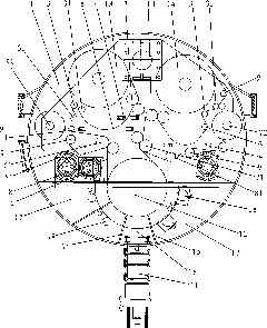
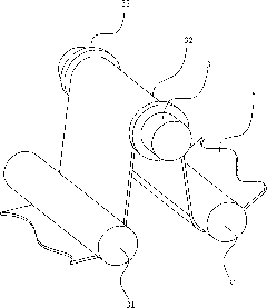
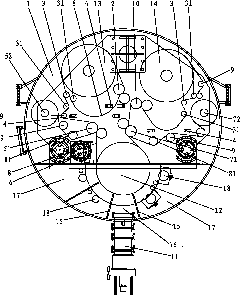
[0031] Below in conjunction with accompanying drawing, the present invention will be further described, see figure 1 and figure 2 As shown, this is a preferred embodiment of the present invention:

[0032] The winding vacuum coating equipment includes a vacuum chamber 1 provided with a vacuum obtaining system, and the vacuum chamber 1 is provided with an unwinding device, a coating chamber and a winding device; the coating chamber is provided with a drive motor output shaft The coating roller 12 that is connected, the coating device 18 of coating chamber is facing the circumferential surface of described coating roller 12; One of the rollers of the unwinding and feeding roller pair 2 is connected to the output shaft of an unwinding and feeding motor, and a tension release roller 3 is arranged between the unwinding and feeding roller pair 2 and the coating roller 12 The winding device includes a winding roller 14 connected to a winding motor output shaft, and a winding feed ...


PUM


Abstract

The invention relates to a winding-type vacuum coater which comprises a vacuum cavity, wherein the vacuum cavity is provided with an unwinding device, a coating chamber and a winding device; the coating chamber is provided with a coating roller connected with the output shaft of a drive motor; the unwinding device comprises an unwinding roller and an active feed rolling wheel pair; a tension release roller is arranged between the active feed rolling wheel pair and the coating roller and used for keeping the loose state of the material roll between the feed rolling wheel pair and the tension release roller; the winding device comprises an active winding roller; a feed rolling wheel pair is arranged between the coating roller and the winding roller; and a tension release roller is arranged between the feed rolling wheel pair and the winding roller. Since the material is kept loose between the feed rolling wheel pair and the tension release roller, the tension change of the unwinding roller and the winding roller due to the gradual change of the material roll diameter can not be transferred to the coating roller, thus, the surface tension of the coated material winding the coating roller is constant, so that the film is uniformly coated with favorable effect.

Description

Technical field: [0001] The invention relates to the technical field of vacuum coating equipment, in particular to a winding vacuum coating equipment. Background technique: [0002] Products coated with functional films on plastic materials such as PET, PE, PI, etc., flexible polymer materials, carbon materials, etc., are widely used in modern industry and high-tech fields. Coating of functional films on strip-shaped substrates mostly adopts the winding coating method. [0003] The processing of the above products generally requires the use of various technologies such as ion beam sputtering, magnetron sputtering, and electron beam evaporation coating in a high vacuum environment. Vacuum coating equipment can obtain one or more uniform deposition layers on conductive substrates and non-conductive substrates, and can be used in EMI, flexible circuit boards, optical coatings and other industries. At present, the widely used vacuum coating machine consists of a vacuum chamber...

Claims


Application Information

Patent Timeline
Patent Type & Authority Applications(China)
IPC IPC(8): C23C14/56C23C14/24
Inventor 袁惠芬
Owner 袁惠芬
Why Eureka
Try Eureka