Ultra-wideband elliptical slot antenna having back chamber

A slot antenna and ultra-wideband technology, which is applied in the field of ultra-wideband elliptical slot antennas, can solve problems such as dissipation and impedance bandwidth reduction, and achieve the effects of reducing gain loss, increasing gain, and improving matchable bandwidth

Active Publication Date: 2009-03-25
SHANGHAI JIAO TONG UNIV
View PDF2 Cites 7 Cited by
  • Summary
  • Abstract
  • Description
  • Claims
  • Application Information

AI Technical Summary

Problems solved by technology

By adding a simple plane reflector on the back of the antenna, the gain has been improved to a certain extent, but the direct introduction of a reflection resonance length leads to a significant drop in impedance bandwidth, and the simple reflector after all leads to a certain degree of surrounding energy Dissipation, there is still room for further improvement in antenna gain

Method used


Image

  • Ultra-wideband elliptical slot antenna having back chamber
  • Ultra-wideband elliptical slot antenna having back chamber
  • Ultra-wideband elliptical slot antenna having back chamber

Examples


Embodiment Construction

[0023] The embodiments of the present invention are described in detail below in conjunction with the accompanying drawings: the present embodiment is implemented under the premise of the technical solution of the present invention, and specific implementation methods and processes are provided, but the protection scope of the present invention is not limited to the following embodiments.

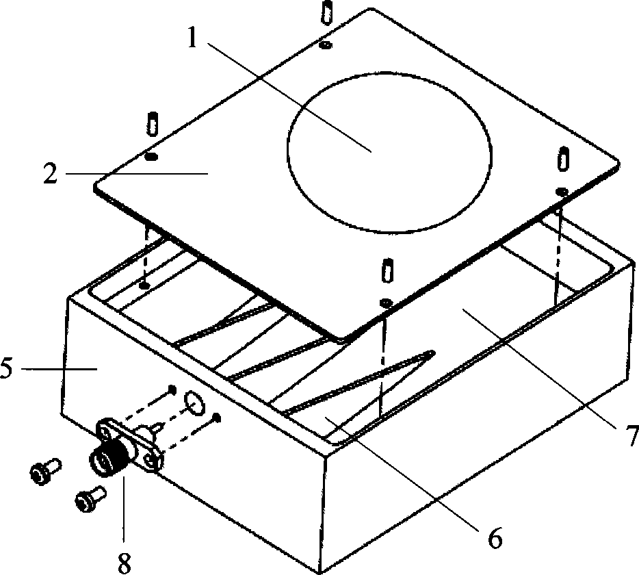
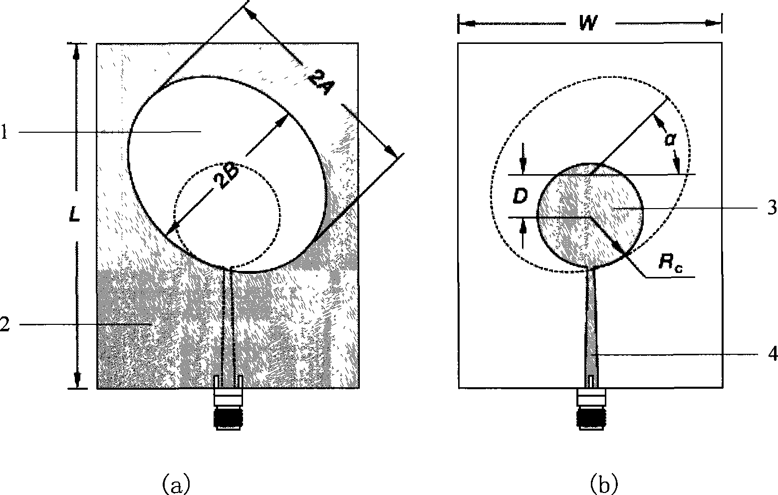
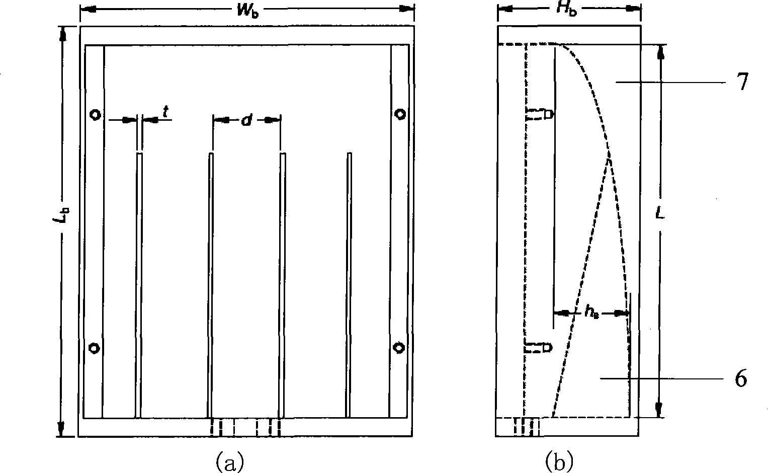
[0024] Such as Figure 1-2 As shown, this embodiment includes a printed medium board 1 and a metal reflection cavity. One side of the printed medium board 1 is a metal ground 2 with a wide slit, the other side is a microstrip feed source, and a tuning chip is added in the metal reflection cavity.

[0025] The wide slit is an elliptical slit and has a rotation angle;

[0026] The microstrip feed source is composed of a circular patch 3 connected to a segment of tapered microstrip feeder line 4 .

[0027] The printing medium board is a low dielectric constant dielectric board 1 .

[0028] ...


PUM


Abstract

The invention relates to an ultra-wideband oval slit antenna with a back cavity in the technical field of the communication. The antenna comprises a printed medium plate and a metallic reflective cavity. A metallic ground with a wide slit is arranged on one side of the medium plate, a micro-band feeding source is arranged on the other side, and tuning sheets are added to the metallic reflective cavity; wherein the wide slit is an oval slit and has a rotation angle; the micro-band feeding source is formed by a circular patch connected with a gradually-changed micro-band line; a plurality of parallel triangular tuning sheets are mounted on one side of the metallic reflective cavity, and an arc-shaped metallic bottom surface is added to the other side. The impedance bandwidth of the oval slit antenna is 3.5-9.65GHz, with the VSWR smaller than 2; the gain of each sampling frequency point is higher than 8dB; the ultra-wideband oval slit antenna has the advantages of high gain, low section and better directional diagram consistency, thereby being used in radar, locating and communication systems and on application occasions requiring high gain, ultra wideband and directional radiation.

Description

technical field [0001] The invention relates to an ultra-wideband antenna in the technical field of communication, in particular to an ultra-wideband elliptical slot antenna with a cavity back. Background technique [0002] As a key component in emerging civil ultra-wideband communication systems, military electronic countermeasure equipment, and pulse radars, ultra-wideband antennas have attracted extensive attention from the research community for many years. Ultra-wideband (UWB) technology originated from the pulse communication technology that emerged in the 1960s. It uses ultra-short pulses with extremely wide spectrum for communication, and is mainly used in military radar, positioning and communication systems. In 2002, the U.S. Federal Communications Commission (FCC) formally passed the proposal to apply the technology to civilian use, and approved the 3.1-10.6GHz frequency band to be designated as the commercial application of ultra-wideband technology. A 500MHz ba...

Claims


Application Information

Patent Timeline
Patent Type & Authority Applications(China)
IPC IPC(8): H01Q13/00H01Q13/10
Inventor 金荣洪耿军平劳佳李忞詝叶声
Owner SHANGHAI JIAO TONG UNIV
Why Eureka
Try Eureka