
Uplink channel measurement reference signal and mapping method for bandwidth range frequency domain position

A technology of reference signal and mapping method, which is applied in the direction of duplex signal operation, selection device, digital transmission system, etc., and can solve problems such as no solution

Inactive Publication Date: 2009-03-25
ZTE CORP
View PDF0 Cites 38 Cited by
  • Summary
  • Abstract
  • Description
  • Claims
  • Application Information

AI Technical Summary

Problems solved by technology

There is currently no corresponding solution

Method used


Image

  • Uplink channel measurement reference signal and mapping method for bandwidth range frequency domain position
  • Uplink channel measurement reference signal and mapping method for bandwidth range frequency domain position
  • Uplink channel measurement reference signal and mapping method for bandwidth range frequency domain position

Examples


example 1

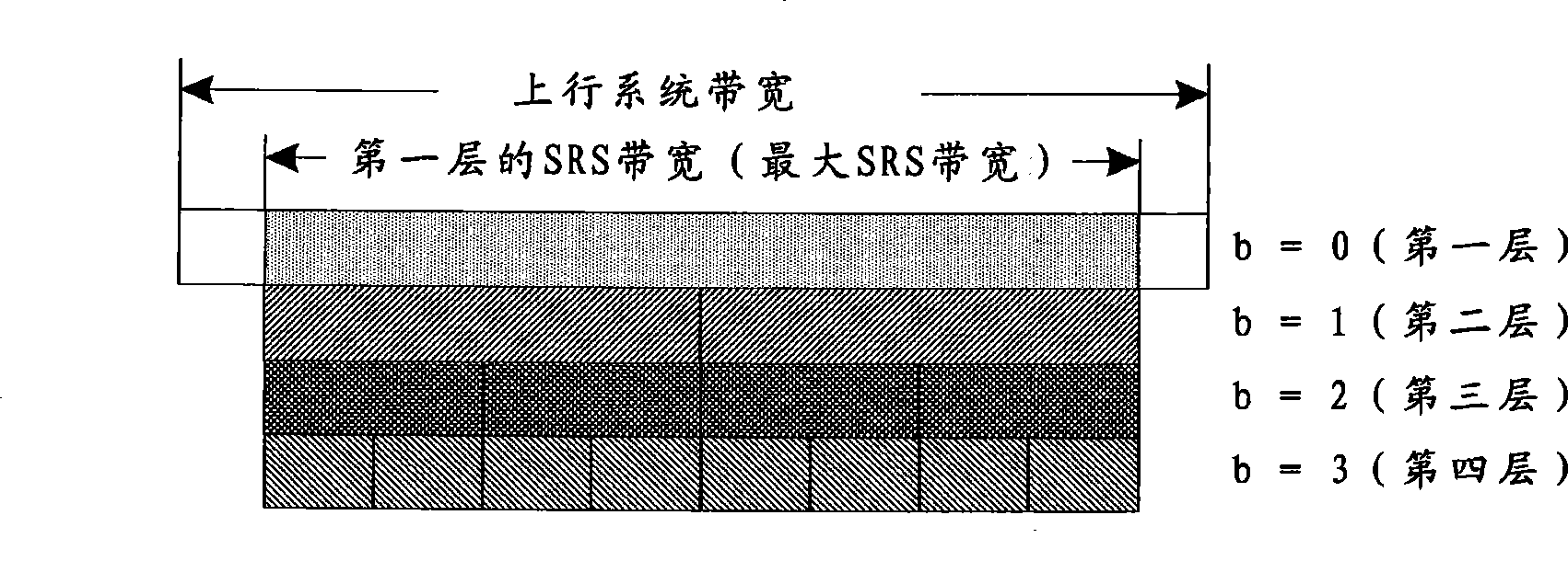
[0082] This example determines the maximum SRS bandwidth according to the first method above, where: the number of RBs corresponding to the uplink system bandwidth in the frequency domain N RB UL = 25 ; The base station selects the SRS bandwidth configuration with index number 4 and notifies the terminal by signaling, and because 6 ≤ N RB UL ≤ 40 , The maximum SRS bandwidth is the SRS bandwidth of the first layer of the tree structure corresponding to the SRS bandwidth configuration with index number 4 in Table 3 above, and the maximum SRS bandwidth corresponds to 16 RBs in the frequency domain, namely m SRS , 0 max = 16 . and have: k TC = 0; n offset,1...

example 2

[0089] This example determines the maximum SRS bandwidth according to the second method above, where the number of RBs corresponding to the uplink system bandwidth N RB UL = 25 , and N RA = 1, n offset,1 =0,n offset,2 =4; then there are: N RB UL - 6 N RA - ( n offset , 2 + n offset , 1 ) = 15 . In all SRS bandwidth configuration tables, among all SRS bandwidth configurations where the number of RBs corresponding to the SRS bandwidth of the first layer in the frequency domain is ≤ 15, the tree structure corre...

example 3

[0096] This example determines the maximum SRS bandwidth according to the first method above, where: the number of RBs corresponding to the uplink system bandwidth N RB UL = 25 ; The base station selects the SRS bandwidth configuration with the index number 4 and notifies the terminal through signaling, because 6 ≤ N RB UL ≤ 40 , The maximum SRS bandwidth is the SRS bandwidth of the first layer of the tree structure corresponding to the SRS bandwidth configuration with the index number 4 in Table 3, and the corresponding RB number of the maximum SRS bandwidth in the frequency domain is 16, namely m SRS , 0 max = 16 ; Otherwise: k TC = 0; n offset,1 = 4;...


PUM


Abstract

The invention discloses a mapping method for uplink channel Sounding Reference Signal and the bandwidth range frequency-domain position. When the frequency-domain position of the largest SRS bandwidth is determined, the frequency-domain position of the largest SRS bandwidth and the physical random accessing channel (PRACH) of the uplink pilot time slot (UpPTS), that is, the frequency-domain position of the PRACH channel are staggered; the distance between the frequency-domain ending position of the largest SRS bandwidth and the upper boundary of the uplink system bandwidth is larger than or equal to an allocated first deviation value, and / or the distance between the frequency-domain initial position of the largest SRS bandwidth and the lower boundary of the uplink system bandwidth is larger than or equal to an allocated second deviation value. The invention has the advantages that interference to the determined frequency-domain position of an SRS signal in UpPTS does not interfere with the PRACH channel, and can avoid out-band leakage between systems.

Description

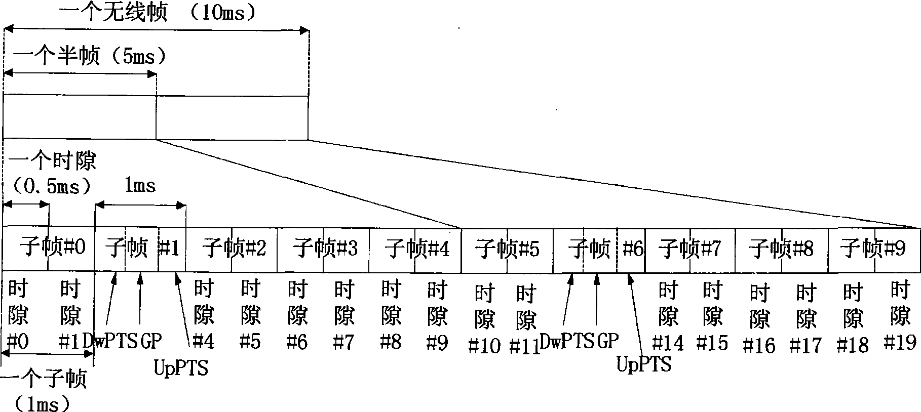
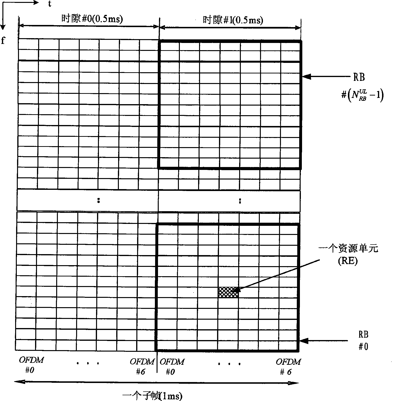
technical field [0001] The present invention relates to a time division duplex (TDD) system, in particular to a method for sending a TDD system uplink channel measurement reference signal. Background technique [0002] The frame structure of the LTE system TDD (Time Division Duplex, time division duplex) mode (also known as the second type of frame structure, namely frame structure type 2) is as follows figure 1 shown. In this frame structure, a radio frame of 10ms (307200Ts, 1ms=30720Ts) is divided into two half-frames, and each half-frame is 5ms long (153600Ts). Each half frame consists of 5 subframes with a length of 1 ms. The role of each subframe is shown in Table 1, where D represents a downlink subframe used to transmit downlink signals. U represents an uplink subframe for transmitting uplink signals. In addition, one uplink or downlink subframe is further divided into two 0.5ms time slots. S represents a special subframe, including three special time slots, name...

Claims


Application Information

Patent Timeline
IPC IPC(8): H04L5/14H04L12/56H04Q7/38H04Q7/22
Inventor 郝鹏喻斌
Owner ZTE CORP
Learn More