
Actuating armature

A technology for actuating components and brakes, applied in the direction of brakes, brake transmissions, fluid-driven clutches, etc.

Inactive Publication Date: 2009-03-25
GUSTAV MAGENWIRTH
View PDF7 Cites 0 Cited by
  • Summary
  • Abstract
  • Description
  • Claims
  • Application Information

AI Technical Summary

Problems solved by technology

[0005] A disadvantage of the above structures is that they have respectively large dimensions due to the storage containers and these storage containers require additional elements such as lids, seals etc.

Method used


Image

  • Actuating armature
  • Actuating armature
  • Actuating armature

Examples


Embodiment Construction

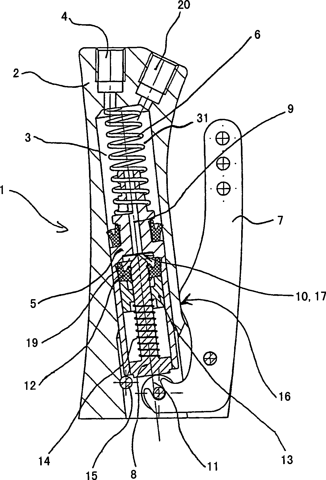
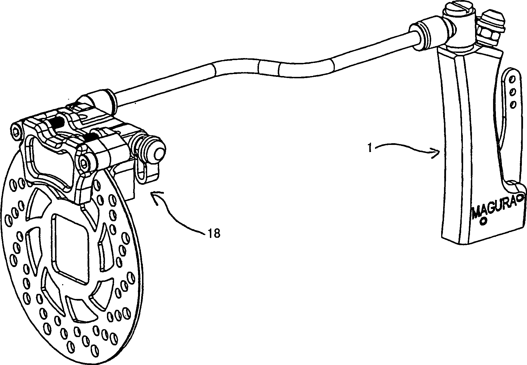
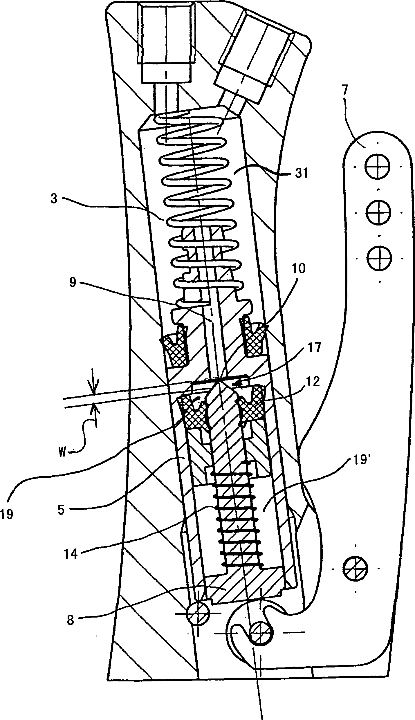
[0082] figure 1 An actuation joint 1 is shown comprising a housing 2 with a substantially cylindrical bore 3 for holding additional elements. Advantageously, the hole 3 serving as a cylindrical space is practically vertical, allowing at the highest point the installation of a vent element 20 through which unwanted air can be expelled, for example by means of a valve not shown . Hydraulic outlet 4 is located in the upper area (see figure 2 ), the fluid volume moved through said hydraulic outlet is passed to at least one actuator 18.

[0083] The piston 5 that moves the fluid when the actuating joint 1 is actuated is located in the cylindrical space 3, is preferably prestressed by a spring element 6 configured as a pressure spring, and can be used, for example, by means of an actuating element via an additional element described below. 7 Applying a force then achieves the stroke established by this structure. The actuating element 7 is preferably configured as a lever or pu...


PUM


Abstract

The invention relates to an actuating armature, in particular brake and / or clutch armature, having a housing (2) in which is arranged a piston (5) which is moveable in a cylinder space (3) by means of an actuating element (7) in order to displace liquid, wherein an equalizing space and / or storage tank (19) is arranged within the cylinder space (3) and / or within the piston (5).

Description

technical field [0001] The invention relates to an actuation joint, in particular an actuation joint of a brake, clutch and / or door lock according to the preamble of claim 1 . Background technique [0002] Such joints are used in particular in monorail or multi-track vehicles as a manual actuation element fixed to the steering wheel or a foot actuation element fixed in the footwell for braking or engaging a clutch. Other applications are also conceivable, for example as an actuating element for triggering and actuating brakes in a vehicle. [0003] German patent publication DE 19601249C2 discloses an actuated joint with a so-called expansion port which, in the unactuated state, establishes a connection between the pressure chamber and the storage container, through which the volumes can be equalized . [0004] European Patent Publication EP 0607370B2 discloses an actuation joint with a so-called central valve positioned inside the piston and which, in the unactuated state,...

Claims


Application Information

Patent Timeline
Patent Type & Authority Applications(China)
IPC IPC(8): B60T11/16F16D25/12
CPCF16D25/08B60T11/165F16D23/12B60T11/22F16D25/12F16D2025/081
Inventor F·凯鲁宾
Owner GUSTAV MAGENWIRTH
Learn More