Insulating switching rod with a contact pressure arrangement comprising a plurality of helical compression springs wound in opposite senses

A joystick and pressure spring technology, which is applied to contacts, contact drive mechanisms, high-voltage air circuit breakers, etc., can solve the problems of coil springs being susceptible to wear and contact force changes, so as to improve bending stability and reduce friction , wear reduction effect

Active Publication Date: 2010-12-08
SIEMENS AG
View PDF6 Cites 0 Cited by
  • Summary
  • Abstract
  • Description
  • Claims
  • Application Information

AI Technical Summary

Problems solved by technology

Such coil springs are subject to wear due to edge wear and, due to their obliquely running characteristic curve, lead to large changes in the introduced contact force with small changes in the working stroke of the switching device

Method used


Image

  • Insulating switching rod with a contact pressure arrangement comprising a plurality of helical compression springs wound in opposite senses
  • Insulating switching rod with a contact pressure arrangement comprising a plurality of helical compression springs wound in opposite senses
  • Insulating switching rod with a contact pressure arrangement comprising a plurality of helical compression springs wound in opposite senses

Examples


Embodiment Construction

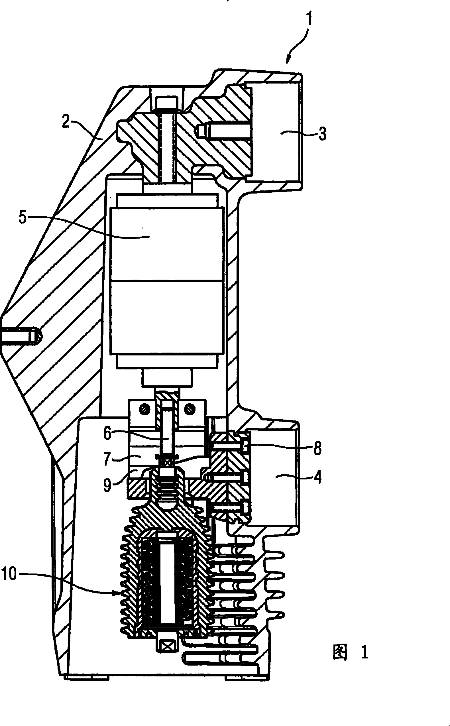
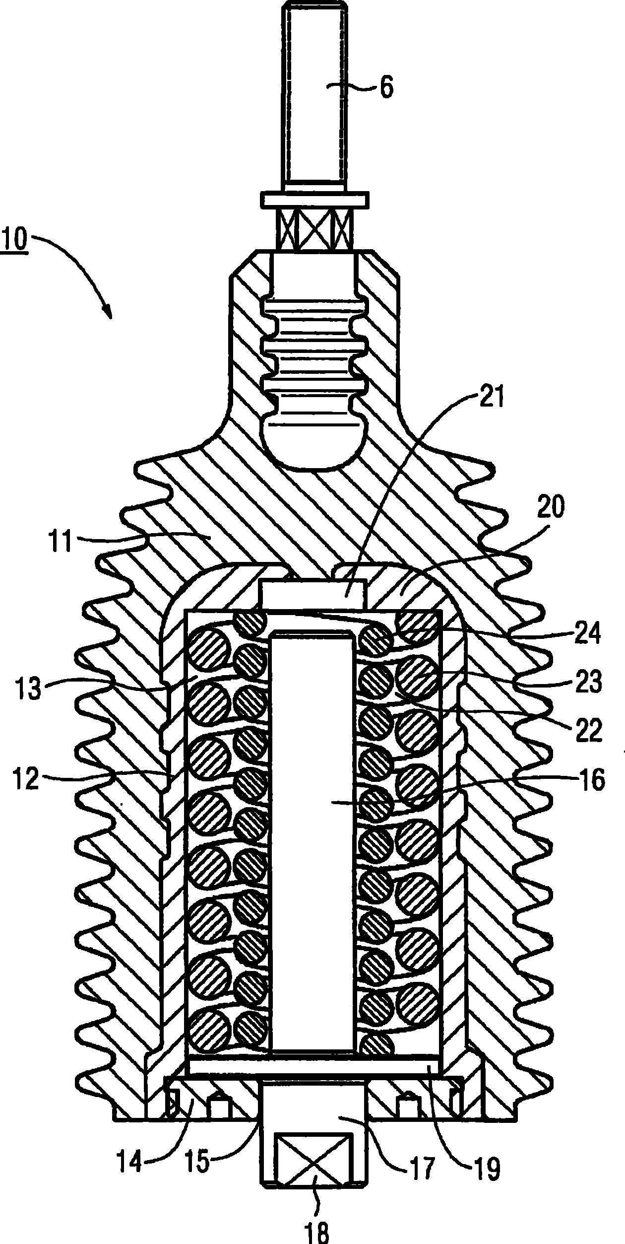
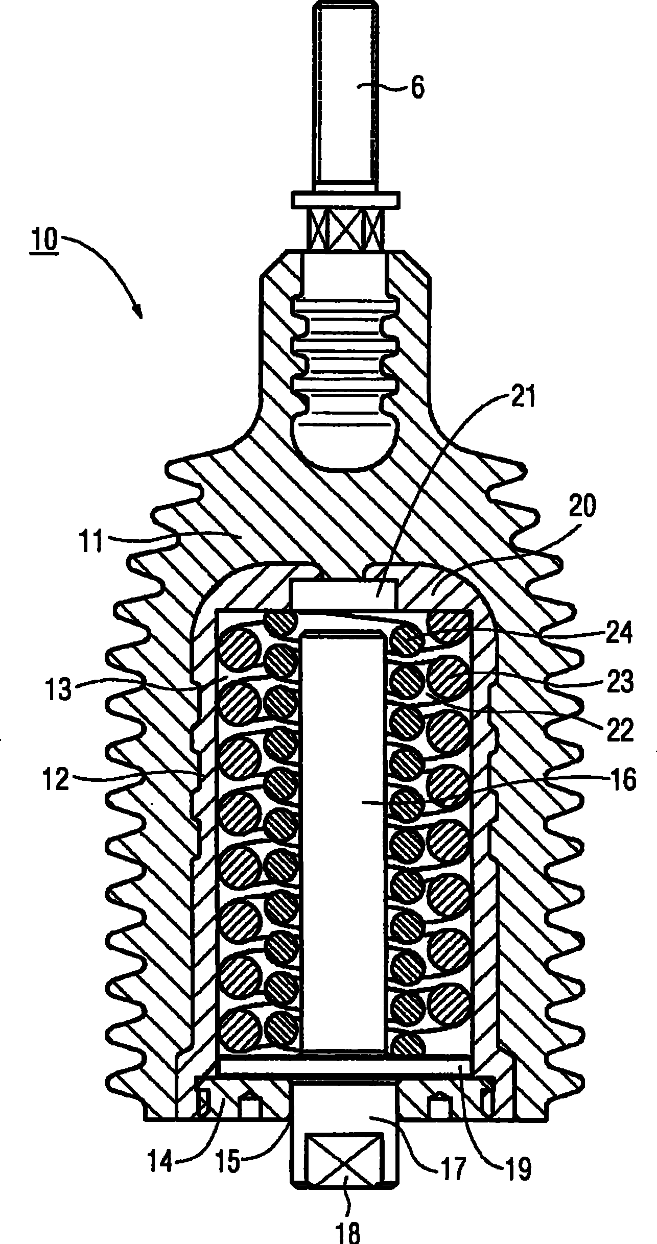
[0013] figure 1 A switching pole 1 of a known circuit breaker of this type for switching or interrupting the current in a polyphase AC network is shown. The switching pole 1 comprises a housing 2 made of insulating material, in which a first connecting part 3 and a second connecting part 4 for connecting busbars or output conductors not shown in the figure of the switching device are arranged. The electrically conductive connection between the first connecting part 3 and the second connecting part 4 can be established or broken via the contact system of the vacuum interrupter 5 . In this case, the not-shown movable contact of the vacuum interrupter 5 is electrically conductively connected to the second connection part 4 by means of a conductive connecting rod 6 via a coupling part 7 or another connection means 8 . Furthermore, the coupling piece 7 has a flexible conductor 9 . Here, the connecting rod 6 is a part of the insulating lever 10, referred to below figure 2 The in...


PUM


Abstract

With regard to an insulating switching rod for initiating a drive movement into a moving contact of an electrical contact system of a switching device, and for producing a contact force when the contact system is in the closed state, with a clamping apparatus which is arranged in a cavity for a drive element of the switching rod in order to maintain the contact force, which has a greater contact force with a compact design, and ensures constant spring characteristics as well as low wear over the entire useful life, it is proposed that the clamping apparatus comprises a helical compression spring arrangement.

Description

technical field [0001] The invention relates to an insulating operating lever for introducing a drive movement into a movable contact of an electrical contact system of a switching device and for generating a contact force in the closed state of the contact system, the insulating operating lever having a spacer Clamping device for the actuator of the joystick in the cavity to maintain the contact force. Background technique [0002] An insulating joystick of this type is known from the known prior art. In switching devices, such as circuit breakers, with an electrical contact system arranged in a vacuum tube, the drive movement is introduced via the drive unit to the movable contact of the electrical contact system. An insulating lever is used on the one hand for the drive unit and the contact system galvanic isolation, and on the other hand for the introduction of drive movement and for the generation of a substantially constant contact force when the contact system is in ...

Claims


Application Information

Patent Timeline
Patent Type & Authority Patents(China)
IPC IPC(8): H01H1/50H01H33/66H01H3/46
CPCH01H33/666H01H2033/6667H01H1/50
Inventor 拉尔夫-赖纳·沃尔克玛托马斯·厄克
Owner SIEMENS AG
Why Eureka
Try Eureka