Vacuum circuit breaker of tank type

A technology of vacuum circuit breaker and vacuum container, which is applied in the setting of high-voltage air circuit breaker, circuit, switchgear with metal casing, etc., can solve problems such as instability, achieve prevention of global warming, reduce overall size, prevent Damaged or damaged effects

Active Publication Date: 2009-03-25
MEIDENSHA ELECTRIC MFG CO LTD
View PDF0 Cites 19 Cited by
  • Summary
  • Abstract
  • Description
  • Claims
  • Application Information

AI Technical Summary

Problems solved by technology

However, since the bellows 25 is made of a thin plate of metal material such as stainless steel, a phenomeno

Method used


Image

  • Vacuum circuit breaker of tank type
  • Vacuum circuit breaker of tank type
  • Vacuum circuit breaker of tank type

Examples


Embodiment Construction

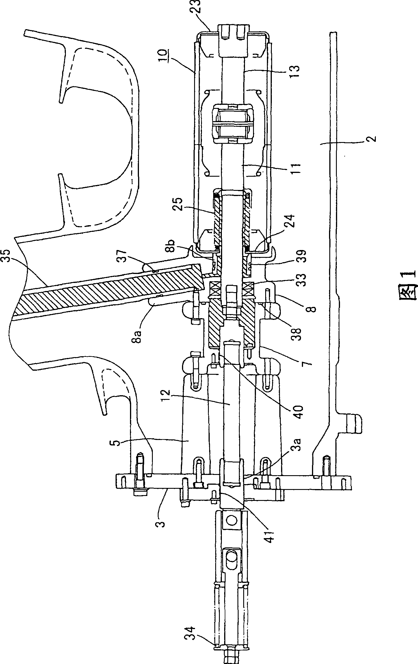
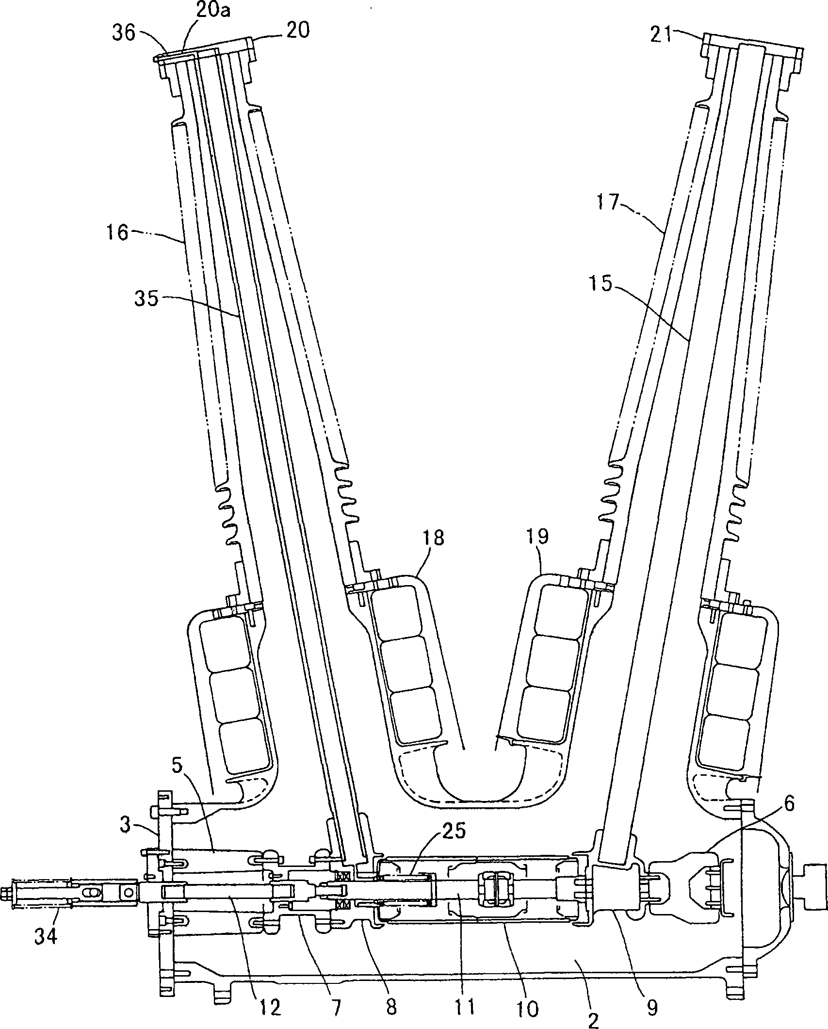
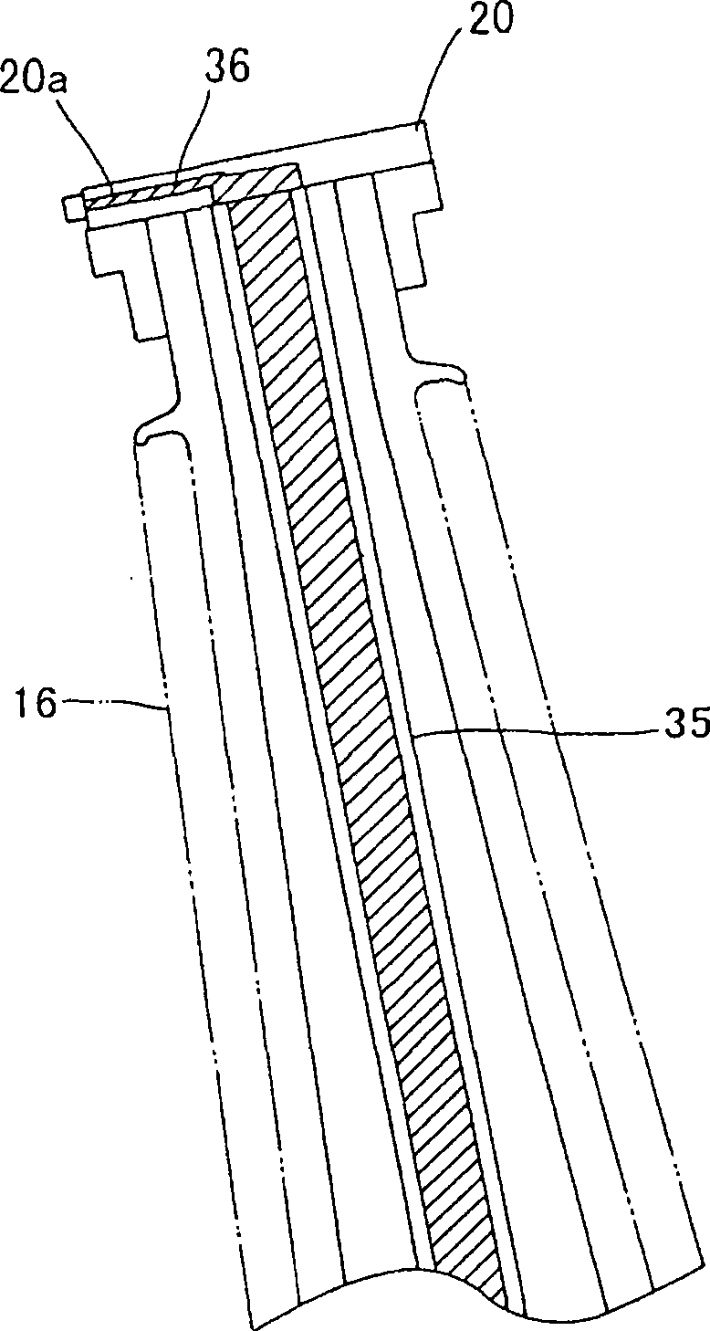
[0028] One and more preferred embodiments of the present invention are described below with reference to the accompanying drawings. Fig. 1 is an enlarged vertical sectional front view of a main body portion of a grounded case vacuum circuit breaker according to a preferred embodiment. figure 2 It is a vertical section front view of a grounded case vacuum circuit breaker. image 3 It is an enlarged vertical cross-sectional view of a part of the movable-side conductor of the grounded case-type vacuum circuit breaker. In Figs. 1 and 3, hatching indicates a portion having atmospheric pressure. In the figure, dry air is sealed in the ground box 2 as a high-voltage insulating gas. High pressure dry air also fills the sleeves 16 and 17 . The support plate 3 is fixed on a horizontal end in the ground box 2 . The movable-side contact box 8 is supported on the inner side of the support plate 3 via the insulating support tube 5 and the insulating support member 7 . The fixed-side c...


PUM


Abstract

To prevent a bellows of a vacuum circuit breaker of tank type from being damaged, reduce the size of the vacuum circuit breaker, and prevent global warming from occurring. A high-pressure dry air is fed into a ground tank (2). A movable contact case (8) is supported at one end inside the ground tank (2) through an insulating supporting tube (5) and an insulating support (7), and a fixed contact case (9) is supported at the other end inside the ground tank (2) through a supporting insulator (6). A vacuum interrupter (10) is supported between the contact cases (8, 9). Bush terminals (20, 21) are connected to the top ends of conductors (35, 15) the bottom ends of which are connected to the contact cases (8, 9). The conductors (35, 15) are surrounded by the bushes (16, 17). The movable conductor (35) is formed in a pipe shape. Hermetical seal parts (37 to 41) are so formed that the inner peripheral side of a bellows (25) the outside of which is vacuum, the inside of the movable conductor (35), the inside of the support (7), and the inside of the movable contact case (8) is kept at the atmospheric pressure and the inside of the insulating support tube (5) is filled with the high-pressure dry air.

Description

technical field [0001] This invention relates to dead tank vacuum circuit breakers for open air use in substations to protect power equipment and for various other applications, and more particularly to internal pressure structures within the tank. Background technique [0002] Figure 4 A vertical sectional front view of a prior art grounded case vacuum circuit breaker is shown. The floor box 2 is supported on the installation workbench 1 . The operation box 4 is fixed to one end of the floor box 2 through the support plate 3 . The operation box 4 includes an operation mechanism inside. The insulating support pipe 5 is supported at one end in the horizontal direction in the floor box 2 by the support plate 3 , and the supporting insulating member 6 is supported at the other end in the horizontal direction in the floor box 2 . The conductive movable-side contact box 8 is supported on the insulating support tube 5 via the insulating support member 7 . The fixed-side conta...

Claims


Application Information

Patent Timeline
IPC IPC(8): H01H33/66H02B13/02
CPCH01H2033/566H01H33/666H01H33/66H02B13/02
Inventor 市川裕己胜又清仁竹下幸宏长竹和浩
Owner MEIDENSHA ELECTRIC MFG CO LTD
Why Eureka
Try Eureka