Arc wide-beam transmission method and device for ultrasonic image-forming

An ultrasonic imaging and transmitting device technology, applied in the re-radiation of sound waves, ultrasonic/sonic/infrasound equipment control, ultrasonic/sonic/infrasound diagnosis, etc., can solve problems such as ultrasonic information distortion

Active Publication Date: 2009-04-01
SHENZHEN MINDRAY BIO MEDICAL ELECTRONICS CO LTD
View PDF2 Cites 17 Cited by
  • Summary
  • Abstract
  • Description
  • Claims
  • Application Information

AI Technical Summary

Problems solved by technology

Since this sound field cannot cover the receiving area of ​​the entire

Method used


Image

  • Arc wide-beam transmission method and device for ultrasonic image-forming
  • Arc wide-beam transmission method and device for ultrasonic image-forming
  • Arc wide-beam transmission method and device for ultrasonic image-forming

Examples


Embodiment Construction

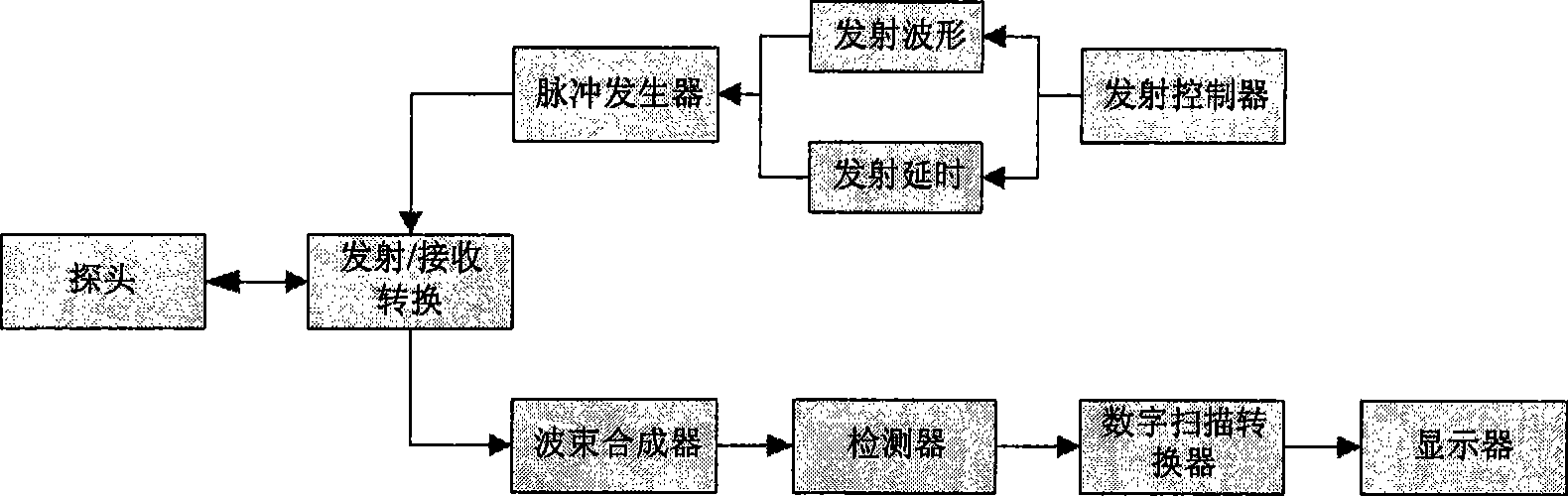
[0026] The frame diagram of the ultrasound system is as follows figure 1 shown. The front end is a probe, and the probe is composed of array elements, each array element has the function of converting electrical signals and acoustic signals, and the probe is connected to the transmitting / receiving conversion part. When the system is in the transmitting state, the transmitting controller provides transmitting waveforms and transmitting delay parameters for each array element as required. The pulse generator excites the probe element according to the transmission waveform and transmission delay, and the probe element converts the electrical signal into an acoustic signal and then transmits it into the detected object. When the system is in the receiving state, the array element in the probe receives the echo of the detected object and converts it into an electrical signal and transmits it to the system, and the system further converts the electrical signal into a digital signal...


PUM


Abstract

The invention discloses a circular arc broad beam emission method for ultrasound imaging and a device thereof. The method comprises a setting step which is used for setting parameters of a focusing circular arc, and a calculating step which is used for calculating emission delay of all array elements in a transmitting aperture based on the set parameters of the focusing circular arc; wherein, a system controls all array element to emit ultrasonic according to the calculated emission delay of all array elements. The circular arc is adopted according to the method, which changes the calculatingmethod of the strong focusing emission delay; therefore, the beam does not focus on one point again so as to obtain the broad beam. Therefore, the method has no special requirement for emission wavesand can be implemented in most ultrasound machines.

Description

technical field [0001] The present invention relates to an ultrasonic imaging system, in particular to a beam emitting method and device for ultrasonic imaging. Background technique [0002] Conventionally, when using a medical ultrasound machine for imaging, the probe element is excited by a transmission signal of a certain frequency and energy to generate a transmission sound beam. During the propagation of the sound beam in the tissue, the energy is gradually weakened due to reflection or absorption. The reflected part propagates to the probe through the tissue, and the array element in the probe receives the reflected signal, which is the ultrasonic echo information of the tissue, and the information is processed by various signals to form an ultrasonic image for display. [0003] Because the conventional single beam needs to have good horizontal resolution, the sound beam should be as narrow as possible, that is, it is hoped that the energy of the beam is only concentra...

Claims


Application Information

Patent Timeline
IPC IPC(8): A61B8/00
CPCA61B8/54G01S7/52095G01S15/892A61B8/00G10K11/346
Inventor 姚斌胡勤军杨鹏飞杨波
Owner SHENZHEN MINDRAY BIO MEDICAL ELECTRONICS CO LTD
Why Eureka
Try Eureka