Supercharge Your Innovation With Domain-Expert AI Agents!

Liquid crystal display device and driving method thereof

A technology of a liquid crystal display device and a driving method, which is applied to static indicators, instruments, etc., can solve the problem of high lower limit voltage and achieve the effect of low lower limit voltage

Inactive Publication Date: 2009-04-01
INNOCOM TECH SHENZHEN +1
View PDF0 Cites 2 Cited by
  • Summary
  • Abstract
  • Description
  • Claims
  • Application Information

AI Technical Summary

Problems solved by technology

[0008] In order to solve the problem of higher lower limit voltage, it is necessary to provide a liquid crystal display device with lower lower limit voltage

Method used


Image

  • Liquid crystal display device and driving method thereof
  • Liquid crystal display device and driving method thereof
  • Liquid crystal display device and driving method thereof

Examples


Embodiment Construction

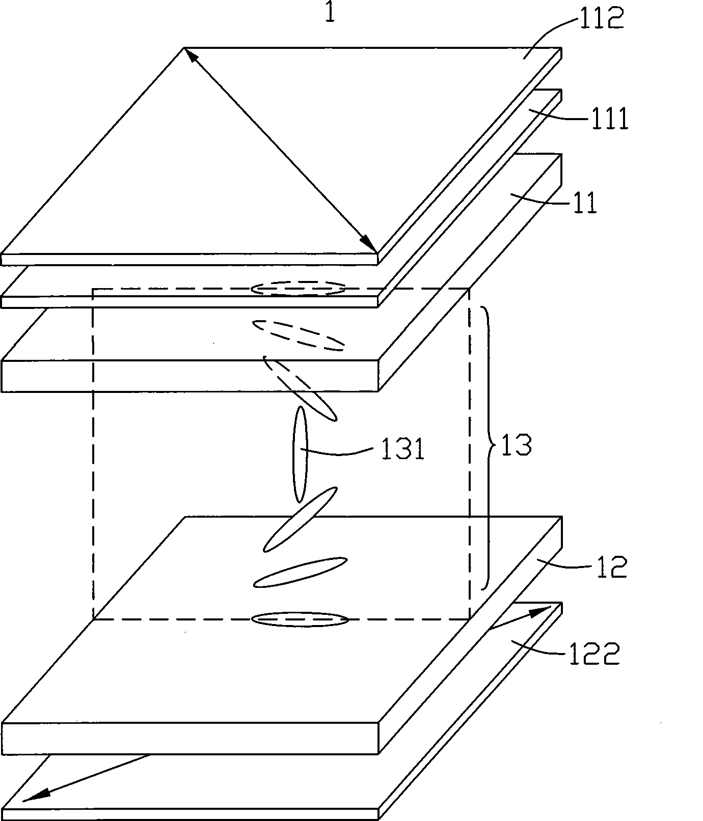
[0023] see Figure 4 , is a schematic structural view of the first embodiment of the liquid crystal display device of the present invention. The liquid crystal display device 2 includes a first substrate 21 , a second substrate 22 opposite to the first substrate 21 , and a liquid crystal layer 23 sandwiched between the two substrates 21 and 22 . The liquid crystal material is a positive type (Δn>0) uniaxial liquid crystal.

[0024] A first polarizer 211 is disposed on the surface of the first substrate 21 away from the liquid crystal layer 23 . A color filter layer 212 , a common electrode 213 and a first alignment layer 214 are sequentially disposed on the surface of the first substrate 21 close to the liquid crystal layer 23 . A second polarizer 221 is disposed on the surface of the second substrate 22 away from the liquid crystal layer 23 . A plurality of pixel electrodes 222 and a second alignment layer 223 are disposed on the surface of the second substrate 22 close to...


PUM


Abstract

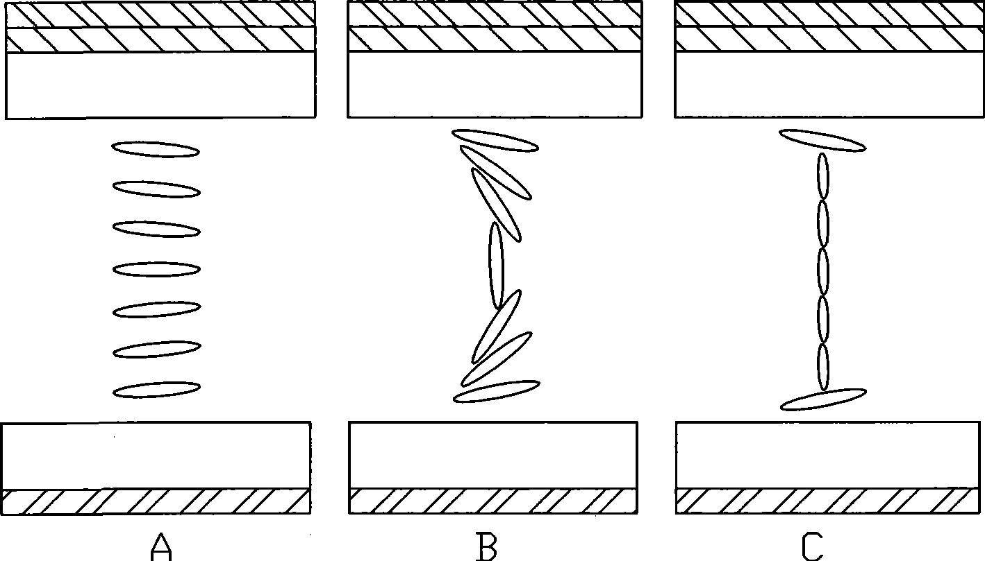
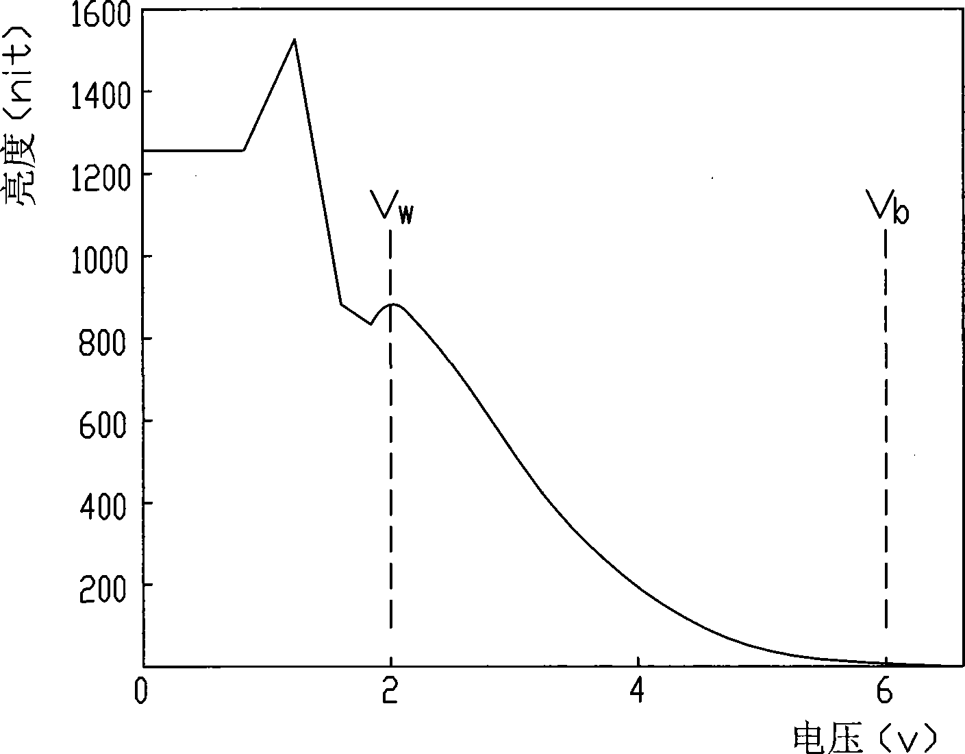
The invention provides a liquid crystal display device and a driving method thereof; the driving method used for the liquid crystal display device comprises the steps as follows: an optical compensation bending typed liquid crystal display device is provided, with the liquid crystal layer arranged horizontally; furthermore, an upper substrate and a lower substrate are arranged in parallel; the optical compensation bending typed liquid crystal display device comprises a plurality of pixel units; each frame time of each pixel unit can be divided into a first sub-frame and a second sub-frame; the first sub-frame displays a black state and the second sub-frame of each pixel unit displays a grey state.

Description

technical field [0001] The present invention relates to a liquid crystal display device and a driving method thereof, in particular to a liquid crystal display device with an Optically Compensated Bend (OCB) structure. Background technique [0002] Liquid crystal display devices have been widely used in the fields of mobile phones, personal digital assistants, notebook computers, personal computers, and televisions due to their low radiation, small size, and low power consumption. With the maturity and innovation of related technologies, their The variety is increasing. [0003] However, liquid crystal display devices also have disadvantages such as slow response speed and low viewing angle, which are especially unfavorable for video products. In response to this defect, various wide viewing angle technologies have emerged accordingly, such as twisted nematic liquid crystal + viewing angle expansion film combination (TN+Film) technology, in-plane switching (In-plane Switchi...

Claims


Application Information

Patent Timeline
Patent Type & Authority Applications(China)
IPC IPC(8): G02F1/133G09G3/36G09G3/20
CPCG09G2310/061G09G3/3648G09G2300/0491
Inventor 姚怡安张淑惠柯宏霖陈鹊如杨秋莲
Owner INNOCOM TECH SHENZHEN
Features
  • R&D
  • Intellectual Property
  • Life Sciences
  • Materials
  • Tech Scout
  • Unparalleled Data Quality
  • Higher Quality Content
  • 60% Fewer Hallucinations
Learn More